
Signal filter module

a technology of signal filter and module, which is applied in the direction of sustainable manufacturing/processing, coupling device connection, and final product manufacturing, etc., can solve the problems of affecting the normal functioning of local area networks, wasting time and labor, and affecting signal transmission, so as to reduce the consumption of terminal materials, save manufacturing costs, and simplify fabrication.

Inactive Publication Date: 2010-06-10
U D ELECTRONIC CORP
View PDF11 Cites 21 Cited by
  • Summary
  • Abstract
  • Description
  • Claims
  • Application Information

AI Technical Summary

Benefits of technology

[0010]The present invention has been accomplished under the circumstances in view. It is one object of the present invention to provide a signal filter module, which diminishes terminal material consumption, saving the manufacturing cost. It is another object of the present invention to provide a signal filter module, which simplifies the fabrication and lowers the defective rate. It is still another object of the present invention to provide a signal filter module, which uses one commonly specification of metal terminals to fit different sizes of electrically insulative housings, simplifying inventory control and saving the cost.
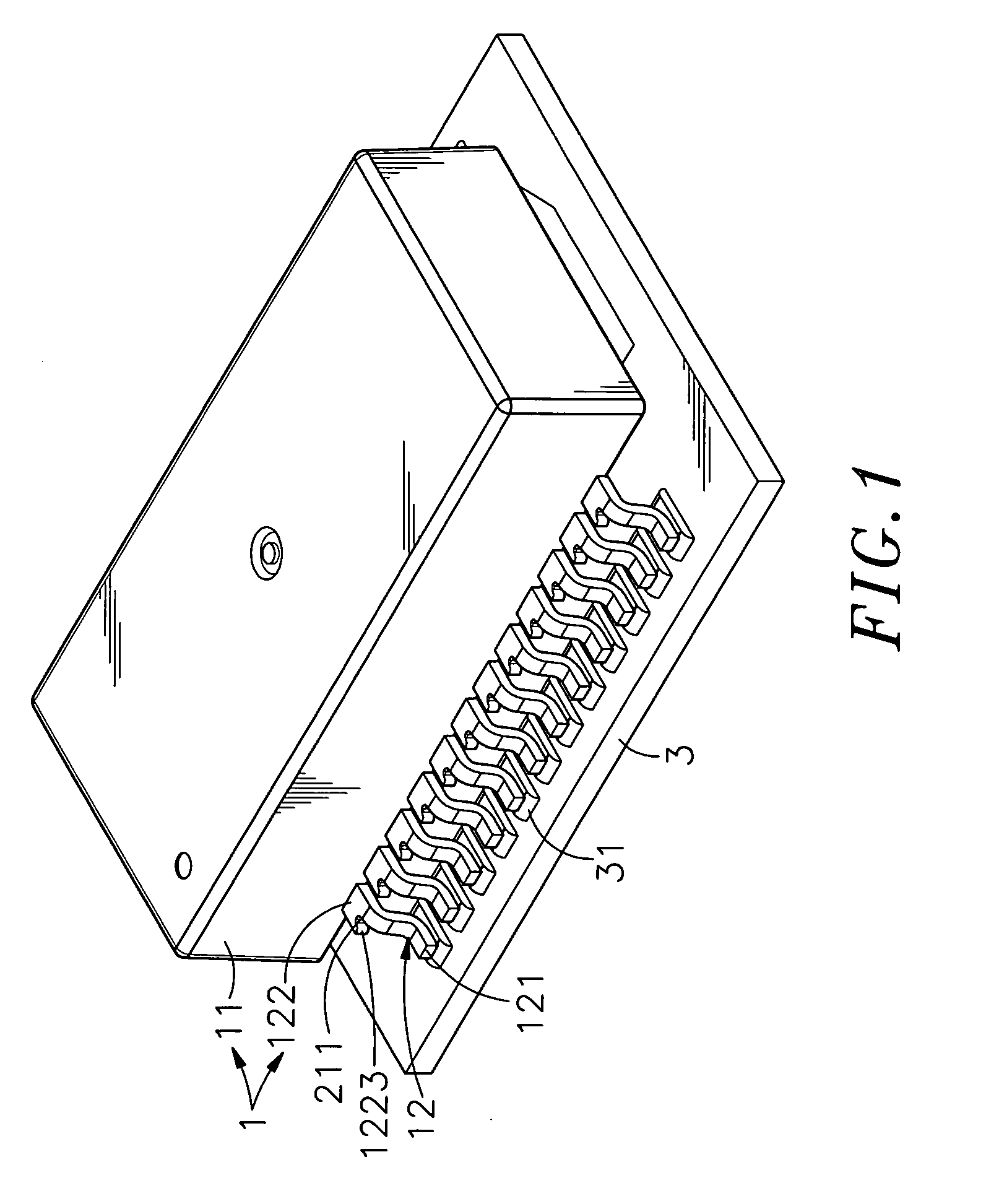
[0011]To achieve these and other objects of the present invention, a signal filter module comprises an electrically insulative housing, a plurality of metal terminals installed in the electrically insulative housing at two opposite sides, and a plurality of filter elements mounted inside the electrically insulative housing and electrically connected to the metal terminals. The metal terminals are directly embedded in two opposite vertical sidewalls of the electrically insulative housing, each having a base exposed to the outside of the bottom edge of the associating vertical sidewall for the bonding of one lead end of one coil of one filter element and a bonding tip thereof suspending outside the electrically insulative housing for bonding to one respective metal contact of an external circuit board. This design needs not to insert the base of each metal terminal through the front and back sides of the associating vertical sidewall so that the metal terminals can be relatively shortened, diminishing terminal material consumption and saving the cost.
[0012]Further, the metal terminals are directly embedded in the vertical sidewalls of the electrically insulative housing that can be configured subject to any of a variety of sizes and specifications to fit different requirements. Therefore, one common specification of metal terminals can be used to fit different sizes of electrically insulative housings, simplifying inventory control and saving the cost.
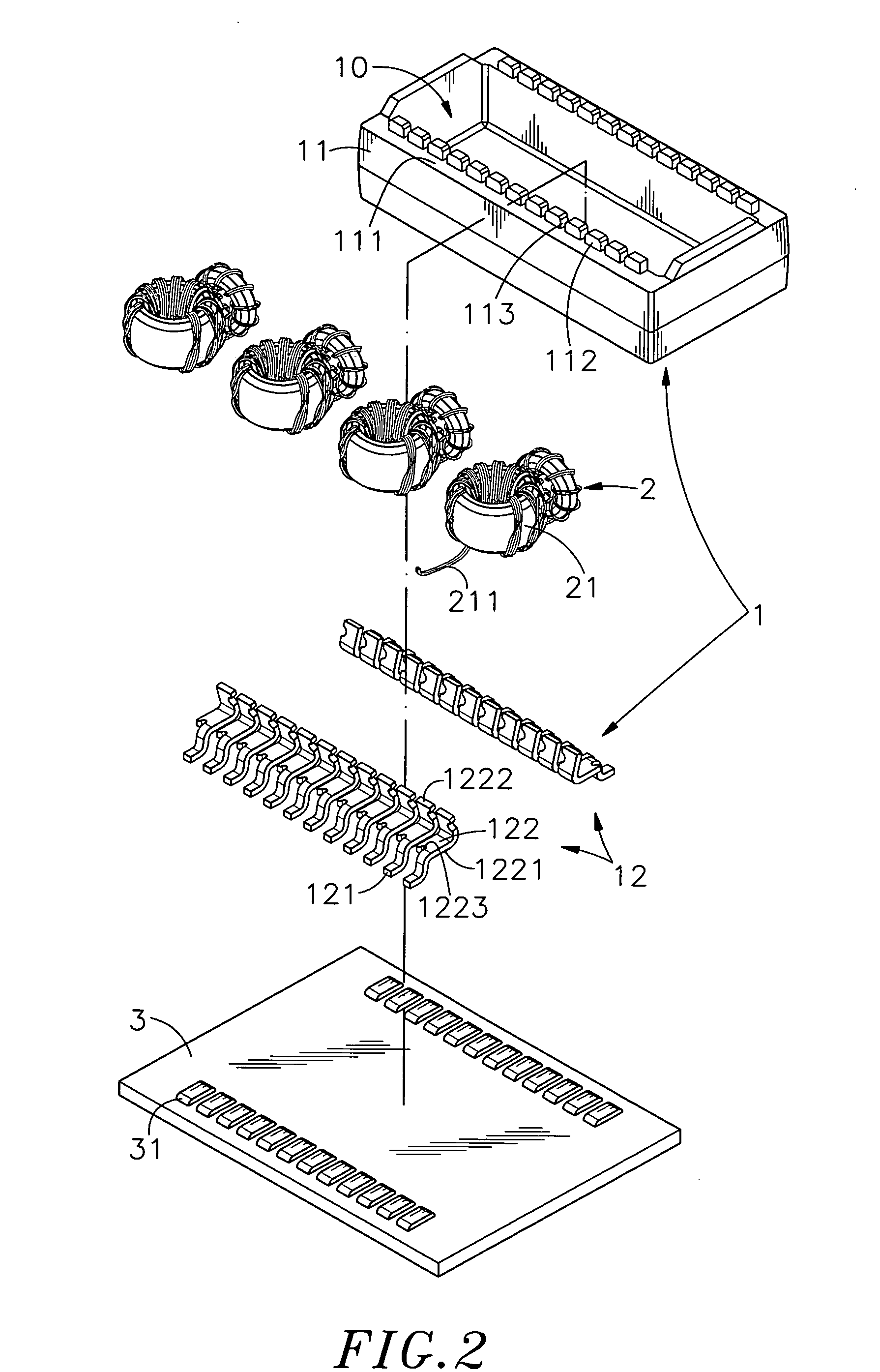
[0013]Further, the electrically insulative housing has a plurality of protruding blocks respectively protruded from the bottom edge of each of the two opposite vertical sidewalls thereof, and a wire groove defined between each two adjacent protruding blocks at each of the two opposite vertical sidewalls. The lead ends of the coils of the filter elements are respectively inserted through the wire grooves of the electrically insulative housing and secured to a respective locating notch on the base of each of the metal terminals for easy bonding to a bonding surface on the base of each of the metal terminals by an automatic soldering machine, lowering the defective rate and simplifying the fabrication.
[0014]Further, the metal terminals can be directly embedded in the vertical sidewalls of the electrically insulative housing by means of insert molding, simplifying the fabrication and saving the manufacturing cost.

Problems solved by technology

Further, during signal transmission of a network interface component, for example, RJ-45 connector, it may cause an electromagnetic interference with surrounding electronic components or circuits, or the surrounding noises may interfere with the transmission of signal through the RJ-45 connector, resulting a signal transmission error.
The electromagnetic interference may disturb surrounding wireless signal transmission, affecting normal functioning of the local area network.
1. Winding the lead wires C1 of the filter elements C round the top pins B2 of the metal terminals B wastes much time and labor, complicating the operation and increasing the cost.
2. Because the metal terminals B extend through the height of the electrically insulative housing A, they must have a certain length, increasing the material cost.
3. Because the top pins B2 of the metal terminals B protrude over the topmost edge of the electrically insulative housing A for the fastening of the lead wires C1 of the filter elements C, the top cover D is necessary for protection. The use of the top cover D complicates the fabrication and cost of the signal filter module.

Method used


Image

  • Signal filter module
  • Signal filter module
  • Signal filter module

Examples


Embodiment Construction

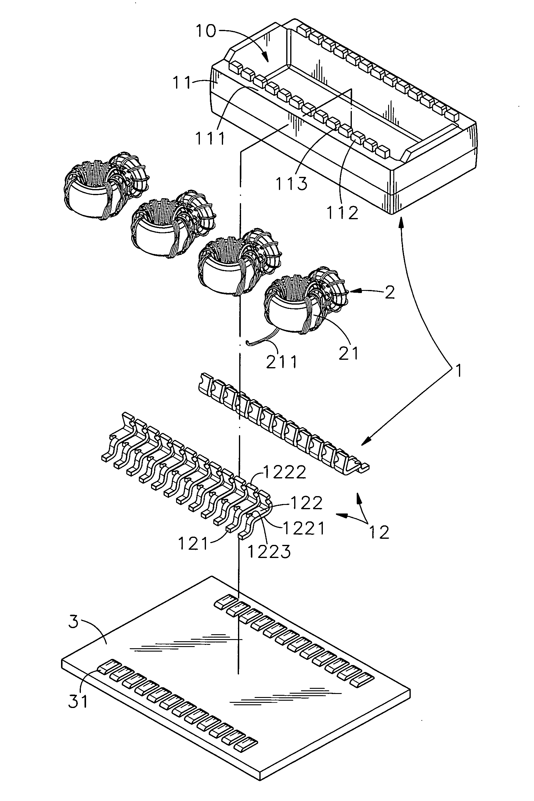
[0023]Referring to FIGS. 1 and 2, a signal filter module in accordance with a first embodiment of the present invention is shown comprising an electrically insulative housing 1 and a plurality of filter elements 2.

[0024]The electrically insulative housing 1 holds a set of metal terminals 12. Further, the electrically insulative housing 1 has an accommodation open chamber 10 opened on the bottom side thereof, two rows of protruding blocks 112 respectively protruded from the bottom edge 111 of each of the two opposite vertical sidewalls 11 thereof, and a wire groove 113 defined between each two adjacent protruding blocks 112 at the bottom edge 111 of each of the two opposite vertical sidewalls 11. The metal terminals 12 are respectively embedded in the two opposite vertical sidewalls 11 of the electrically insulative housing 1 near the associating protruding blocks 112 and wire grooves 113 for bonding to respective metal contacts 31 at a circuit board 3. Each metal terminal 12 has a b...


PUM


Abstract

A signal filter module includes an electrically insulative housing having protruding blocks respectively protruded from the bottom edge of each of two opposite vertical sidewalls thereof and a wire groove defined between each two adjacent protruding blocks, metal terminals each having a base partially embedded in one of the vertical sidewalls of the electrically insulative housing and partially exposed to the outside of the associating vertical sidewall to provide a bonding surface and a bonding tip extended from one end of the base and suspending outside the electrically insulative housing for bonding to an external circuit board, and filter elements each having coils wound thereon with lead ends of the coils respectively inserted through the wire grooves of the electrically insulative housing and bonded to the bonding surfaces of the bases of the metal terminals.

Description

BACKGROUND OF THE INVENTION[0001]1. Field of the Invention[0002]The present invention relates to signal filter technology and more particularly, to a signal filter module, which has metal terminals directly embedded in two vertical sidewalls of an electrically insulative housing for the bonding of lead ends of coils of filter elements accommodated in the electrically insulative housing by an automatic soldering machine, simplifying the fabrication and saving the cost.[0003]2. Description of the Related Art[0004]Following development of electronic information products toward fine and delicate design, SMT (Surface Mount Technology) is commonly used for the bonding of electronic components to a circuit board. Further, during signal transmission of a network interface component, for example, RJ-45 connector, it may cause an electromagnetic interference with surrounding electronic components or circuits, or the surrounding noises may interfere with the transmission of signal through the ...

Claims


Application Information

Patent Timeline
IPC IPC(8): H05K7/02
CPCH01F17/062H01F27/027H01F27/292H01F41/10H01F2005/043H05K2201/10287H01R13/719H03H2001/0092H05K3/3426H05K2201/1003H05K2201/1006H01R13/6633Y02P70/50
Inventor CHEN, PO-JUNG
Owner U D ELECTRONIC CORP
Learn More