Microscope

a microscope and optical technology, applied in the field of microscopes, can solve the problem of extremely conspicuous fringes of light interferen

Inactive Publication Date: 2010-06-10
NIKON CORP
View PDF4 Cites 20 Cited by
  • Summary
  • Abstract
  • Description
  • Claims
  • Application Information

AI Technical Summary

Benefits of technology

[0012]According to a second aspect of the present invention, there is provided a microscope that illuminates a sample with laser light from a laser light source through an objective lens and makes it possible to observe the sample through the objective lens, the microscope including, a polarizer that is disposed on an optical path between the laser light source and the objective lens and produces linearly polarized light, wherein the laser light source is disposed such that a converging point of the laser light is disposed at a position conjugate with a pupil of the objective lens, and the laser light is positioned where laser light is incident on the sample with a Brewster angle.

Problems solved by technology

Moreover, since the background of the sample image is nearly total darkness and S / B ratio (signal / background ratio) is high, even slight interference fringes tend to be extremely conspicuous.

Method used


Image

  • Microscope
  • Microscope
  • Microscope

Examples


first embodiment

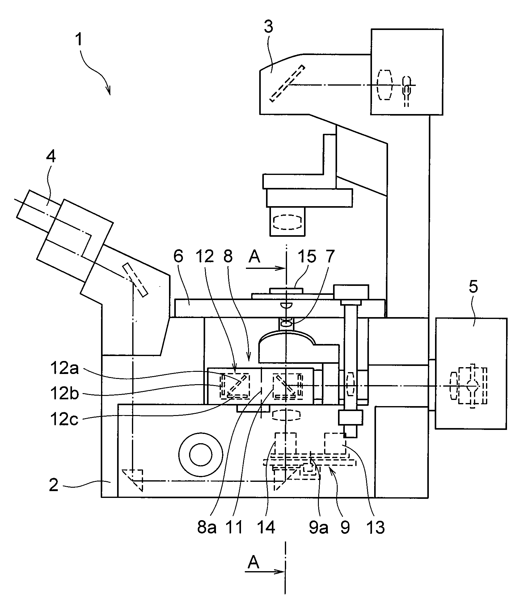
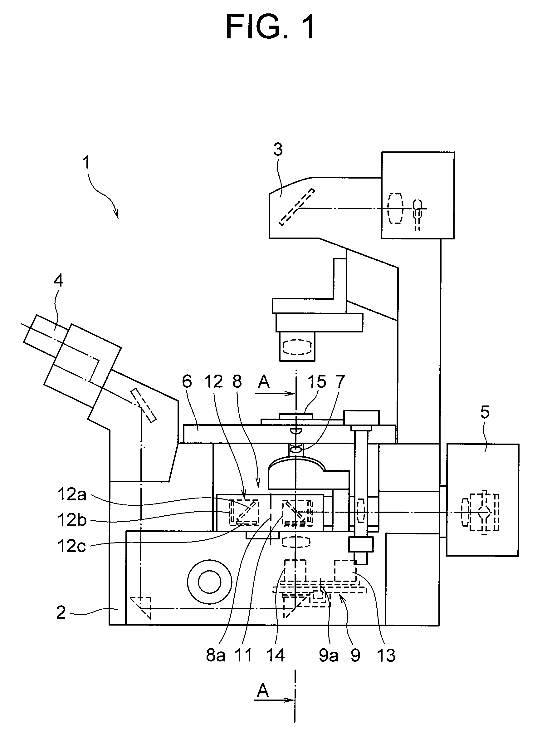
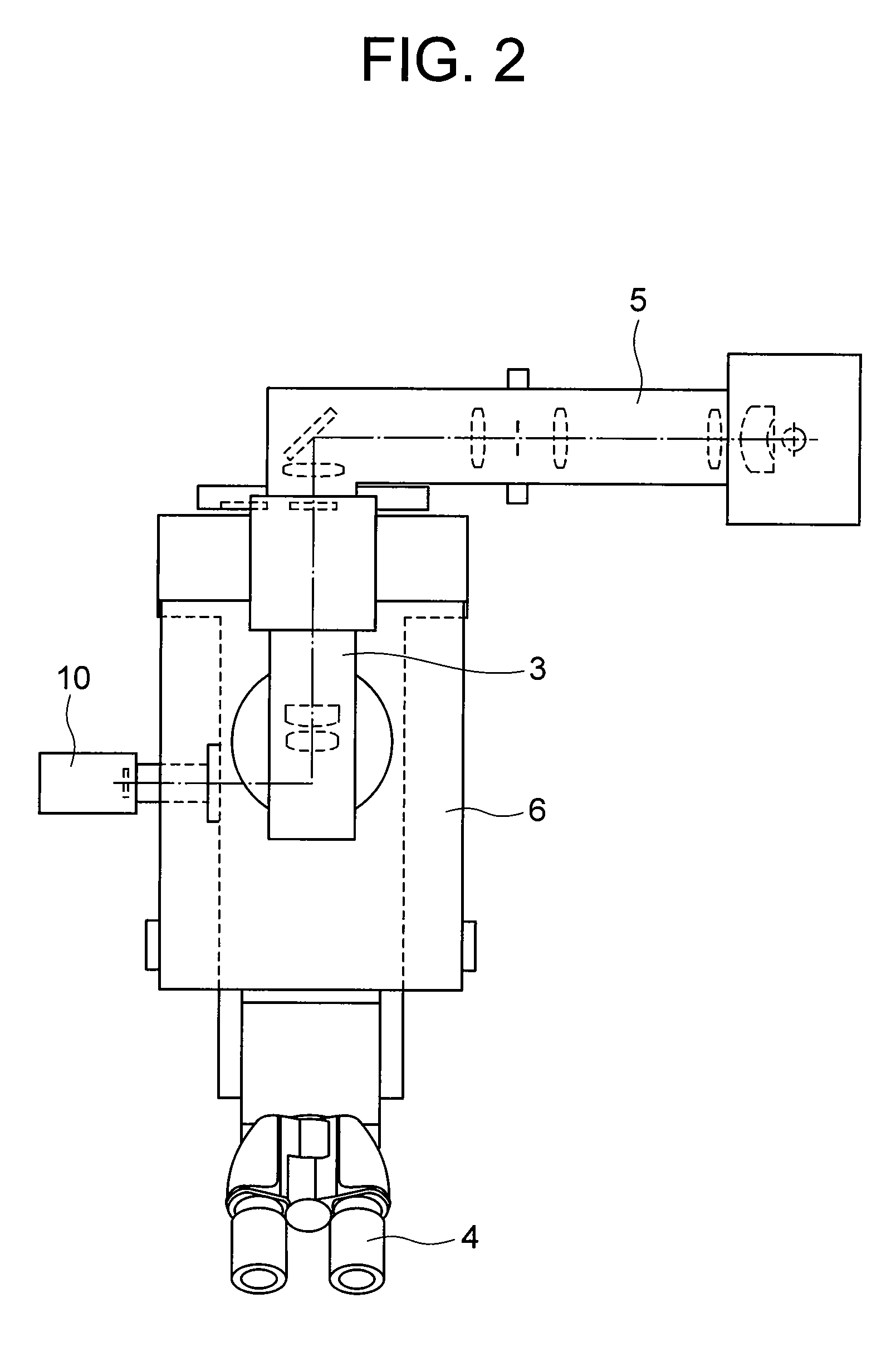
[0032]FIGS. 1 and 2 views showing a configuration of an inverted microscope according to a first embodiment in which FIG. 1 is a side view and FIG. 2 is a top view.

[0033]As shown in FIG. 1, the inverted microscope 1 according to the first embodiment is composed of a microscope base 2, a diascopic illumination device 3 disposed upper side of the microscope base 2, an eyepiece tube 4, and an episcopic illumination device 5 disposed on a side of the microscope base 2.

[0034]On top of the microscope base 2, there is disposed a stage 6 on which a sample is placed. In the microscope base 2, there are disposed, in order from the stage 6 downward, an immersion objective 7 with a high numerical aperture, a block exchange unit 8, and an optical path exchange unit 9. As shown in FIG. 2, there is disposed a CCD camera 10 on the other side of the microscope base 2 shown in FIG. 1.

[0035]The block exchange unit 8 is equipped with a beam splitter 11 and a fluorescence filter block 12, and is able to...

second embodiment

[0072]In an inverted microscope according to a second embodiment of the present invention, a portion that has the similar configuration as the inverted microscope according to the first embodiment is attached with the same symbol and the explanation thereof is omitted, and a distinctive portion is explained in detail.

[0073]FIG. 6 is a side view showing a configuration of an inverted microscope according to the second embodiment of the present invention. FIGS. 7 and 8 are a view and a partially enlarged view, respectively, showing an episcopic illumination device according to the second embodiment of the present invention.

[0074]As shown in FIG. 6, in a microscope base 2 in an inverted microscope 50 according to the present embodiment, there is provided an analyzer 51 between a beam splitter 11 and an optical path exchange unit 9, which is removable from the optical axis and adjustable in a rotatable manner around the optical axis.

[0075]As shown in FIGS. 6 and 7, in the episcopic illu...


PUM


Abstract

A microscope for introducing light from a light source via an objective lens to a sample so that a user observes the sample via the objective lens includes: a minute opening arranged in an optical path between the light source and the objective lens and on a focal plane of the image side of the objective lens or at a position conjugate with its conjugate plane; position adjusting means for adjusting the position of the minute opening so that the light from the light source via the minute opening is incident to the sample at the Brewster's angle; an polarizing element arranged in the optical path between the light source and the objective lens for extracting rectilinear polarized light from the light from the light source and applying the rectilinear polarized light to the sample.

Description

TECHNICAL FIELD[0001]The present invention relates to a microscope.BACKGROUND ARTSBrewster Microscope[0002]It has been well known since 19th century that reflectance of p-polarized light becomes zero when the incident angle becomes Brewster angle. Dirk Honig and Dietmar Mobius, and S. Henon and J. Meunier reported in 1991 that observation of a monolayer could be performed by using this phenomenon. Since then, research on imaging reflectance distribution of a thin film has become active.[0003]The phenomenon has been used mainly for structural observation of a monolayer such as two-dimensional structure of a Langmuir monolayer spread at a gas-liquid interface on a liquid, phase separation of a mixed Langmuir monolayer, and Langmuir-Blodgett film formed on a substrate. An imaging apparatus thereof is now put on the market, and used for evaluating a thin film in a semiconductor manufacturing process, and for product inspection of a DNA micro-array used in a DNA examination.[0004]In such...

Claims


Application Information

Patent Timeline
Patent Type & Authority Applications(United States)
IPC IPC(8): G02B21/06G02B21/00
CPCG02B21/082G02B5/3066
Inventor SUGIURA, TADAOYASAKA, KATSUHIKOKAWAHITO, TAKASHIMATSUI, KUMIKO
Owner NIKON CORP
Why Eureka
Try Eureka