
Method and arrangement for actuation

Inactive Publication Date: 2010-06-03
SWAGELOK CO
View PDF9 Cites 28 Cited by
  • Summary
  • Abstract
  • Description
  • Claims
  • Application Information

AI Technical Summary

Benefits of technology

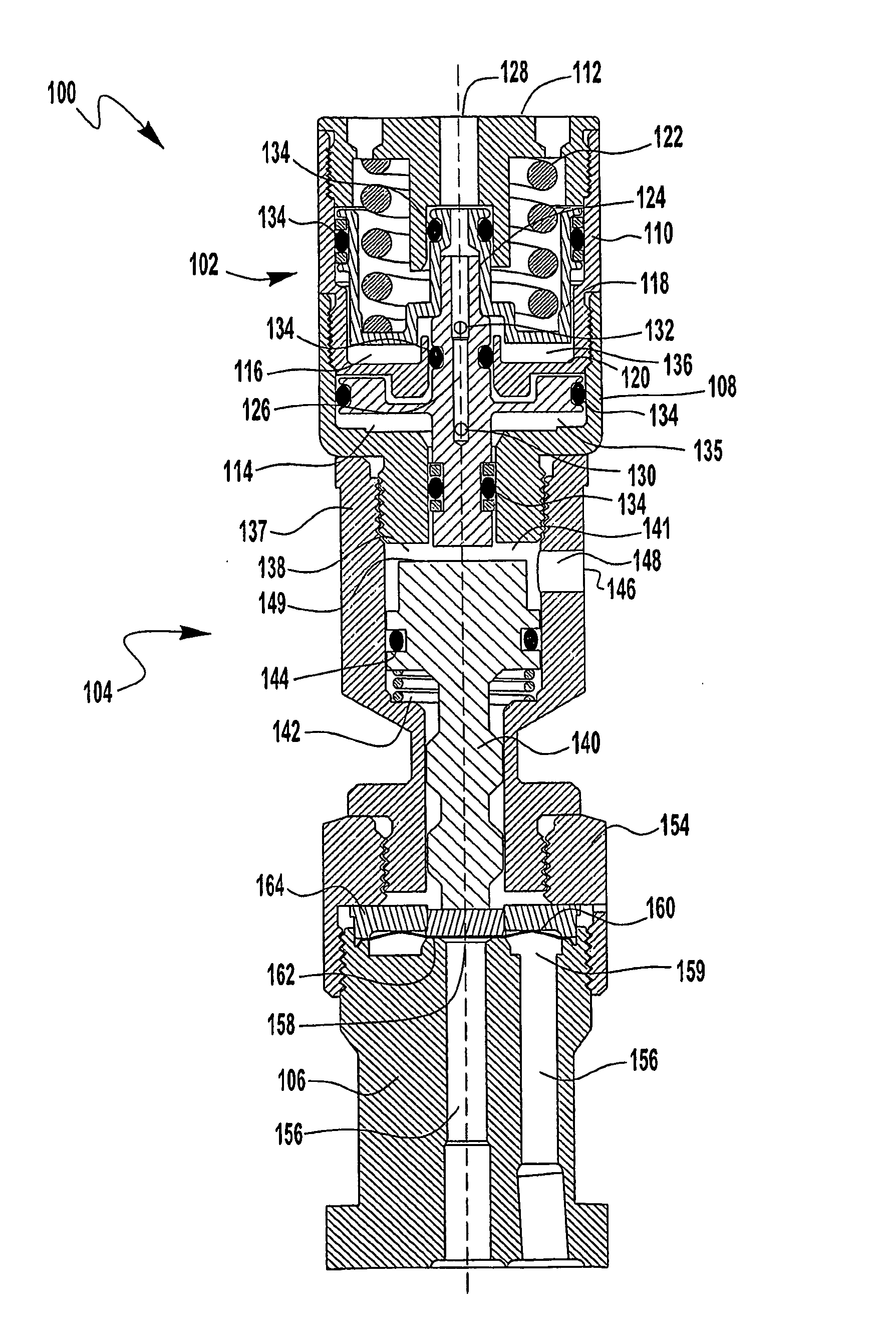
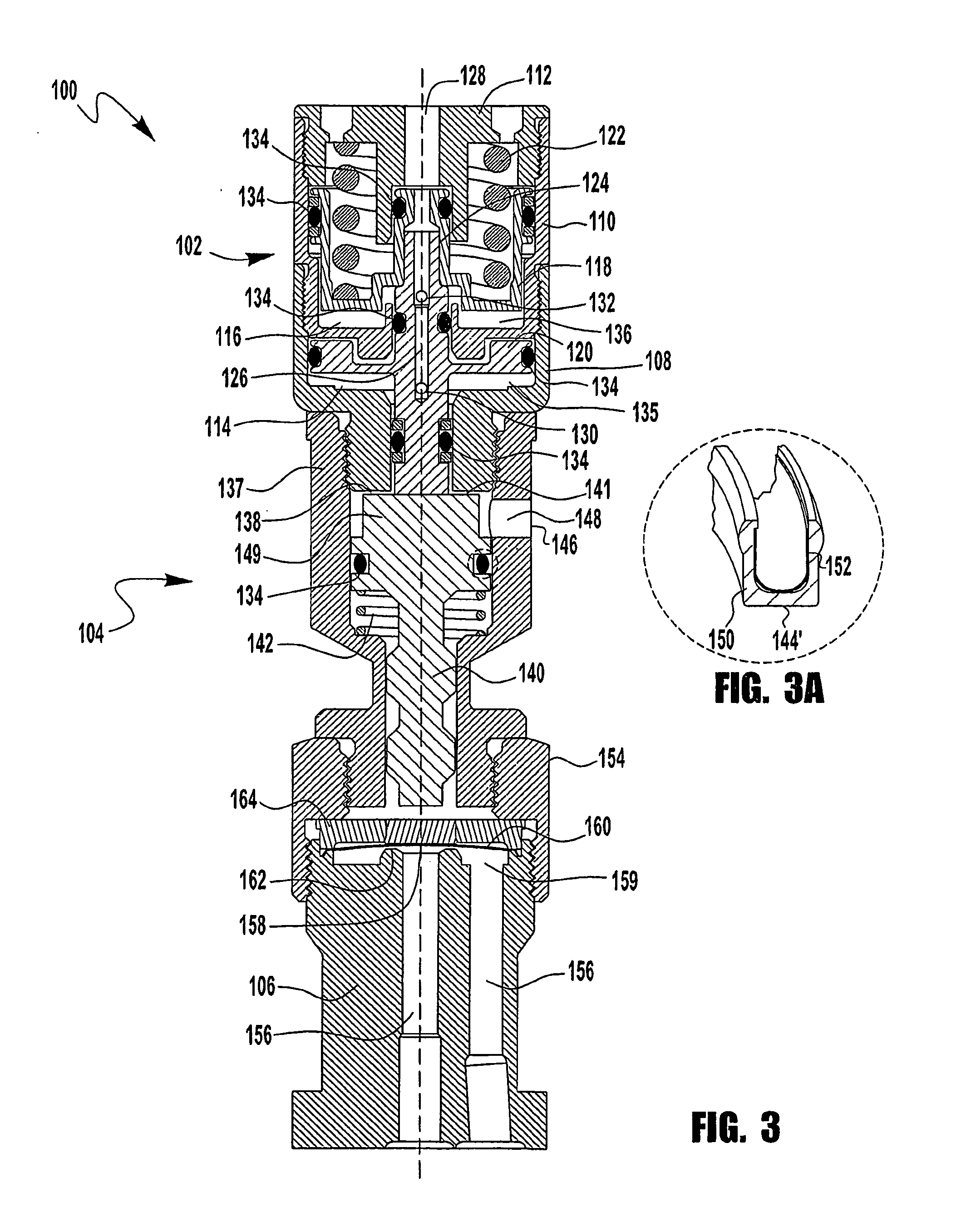
[0006]Another inventive concept disclosed in the application relates to providing a predetermined, time dependent output force. In one embodiment, in a first mode of operation, a first amount of output force may be provided by an arrangement. In a second mode of operation, an offsetting actuation force may be provided to reduce the output force to a second level. Over a predetermined time, the offsetting actuation force may be removed. In a more specific embodiment, a pressure driven actuator provides an actuation force and an arrangement prevents complete depressurization of the actuator during one mode but allows for a slow release of pressure from the actuator in another mode.

Problems solved by technology

Sealing members, however, are more prone to wear or damage when higher sealing forces are used, especially in high cycle frequency or extended cycle applications.

Method used


Image

  • Method and arrangement for actuation
  • Method and arrangement for actuation
  • Method and arrangement for actuation

Examples


Embodiment Construction

[0019]While the exemplary embodiments described herein are presented in the context of an arrangement including an actuator coupled to a normally-closed valve or an actuator actuated by biasing members and fluid pressure, those skilled in the art will readily appreciate that the present invention may be configured in other ways. For example, the arrangement may be configured to use a separate actuator coupled to an actuated device or have the actuating functionality integral with the actuated device. Further the arrangement may be configured to include different actuators, such as for example, a hydraulic actuator, different actuated devices, such as for example, a normally open valve or a device other than a valve. These examples and the disclosed exemplary embodiments are intended to illustrate the broad application of the inventions and are intended to provide no limitation on the present inventions.

[0020]While various inventive aspects, concepts and features of the inventions ma...


PUM


Abstract

The present application relates to an arrangement for selectively providing a plurality of output forces, such as for example, a higher and a lower output force or a predetermined, time dependent output force. In one embodiment, a first piston assembly is moveable between a first and a second position and a second piston assembly moveable between a third and a fourth position. When the first piston assembly is in the first position, the second piston assembly is selectively movable between the third position and the fourth position. When the first piston assembly moves the second position, it moves the second piston assembly to the fourth position.

Description

RELATED APPLICATIONS [0001]This application claims the benefit of U.S. provisional patent applications Ser. No. 60 / 698,889 for DUAL MODE ACTUATOR filed Jul. 13, 2005, and Ser. No. 60 / 750,452 for METHOD AND ARRANGEMENT FOR DUAL MODE ACTUATION filed Dec. 14, 2005, the entire disclosures of which are fully incorporated herein by reference.BACKGROUND OF THE INVENTION[0002]Some processes may require a valve that actuates at a high cycle frequency. In other words, the valve opens and closes with a relatively small amount of time between opening and closing events. High frequency actuators are often used to actuate the valves in these applications. One process that utilizes high frequency actuators is atomic layer deposition (ALD). ALD is a process that utilizes actuators to open and close valves rapidly to deposit very thin layers of various reactive materials or chemicals on the surface of a substrate. A typical ALD process may require, for example, tens to hundreds of actuation cycles o...

Claims


Application Information

Patent Timeline
IPC IPC(8): G05D15/01F16K25/00F16K31/12G05D7/06G05D16/20
CPCF15B11/036F15B11/123F15B15/1409F16K31/1226F15B2211/7055F15B2211/76F16K31/1225F15B15/24F16K31/122F15B15/14
Inventor GLIME, WILLIAM H.
Owner SWAGELOK CO
Learn More