High power optical disc drives
a high-power, optical disc technology, applied in the field of optical disc drives, can solve the problems of low cost, affecting the size and weight of the disc drive, and the power of the laser is typically much higher than the power, and achieves the effect of high power
- Summary
- Abstract
- Description
- Claims
- Application Information
AI Technical Summary
Benefits of technology
Problems solved by technology
Method used
Image
Examples
##ic example 1
Prophetic Example 1
Preparation of a High-Powered Disc Drive
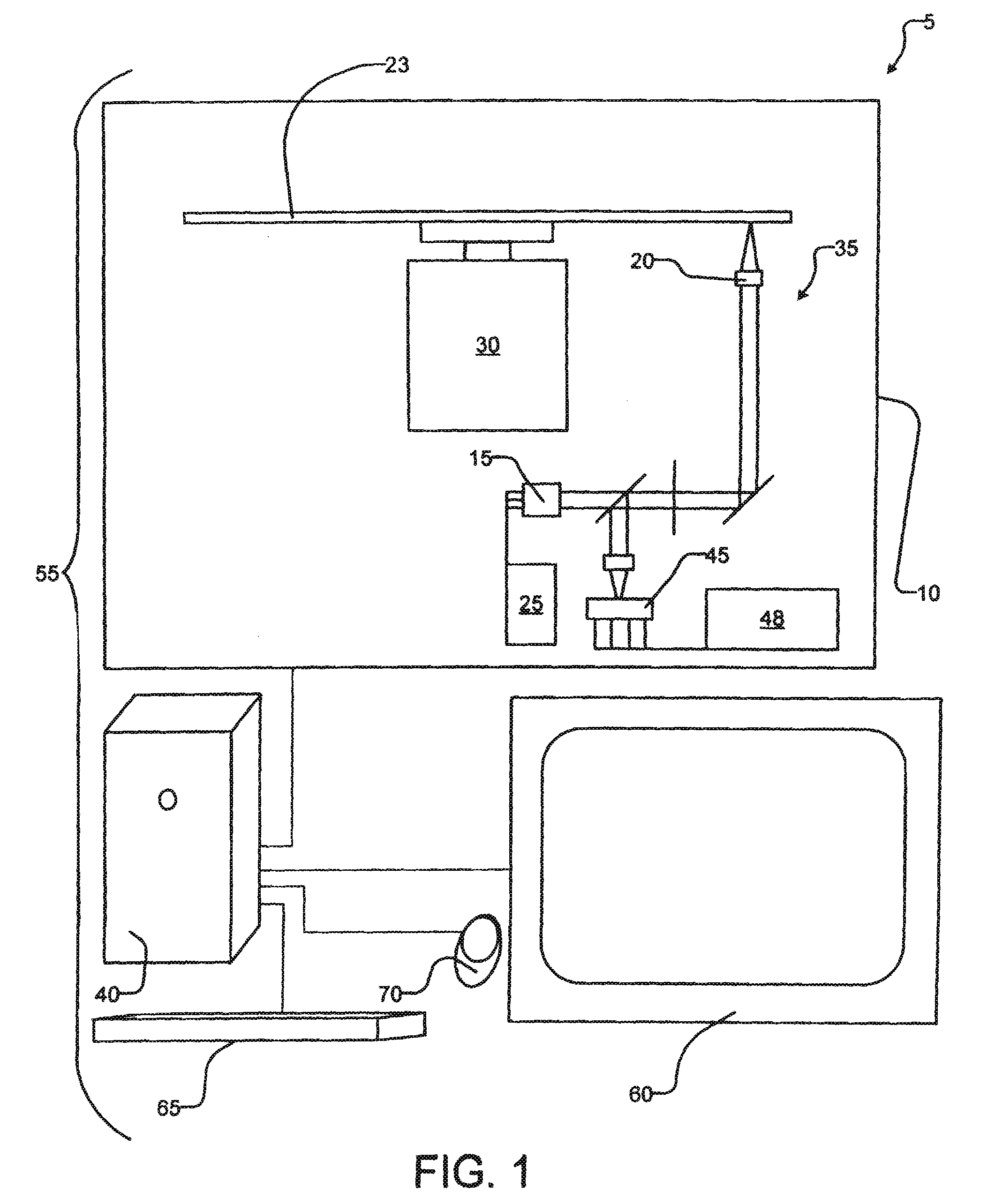
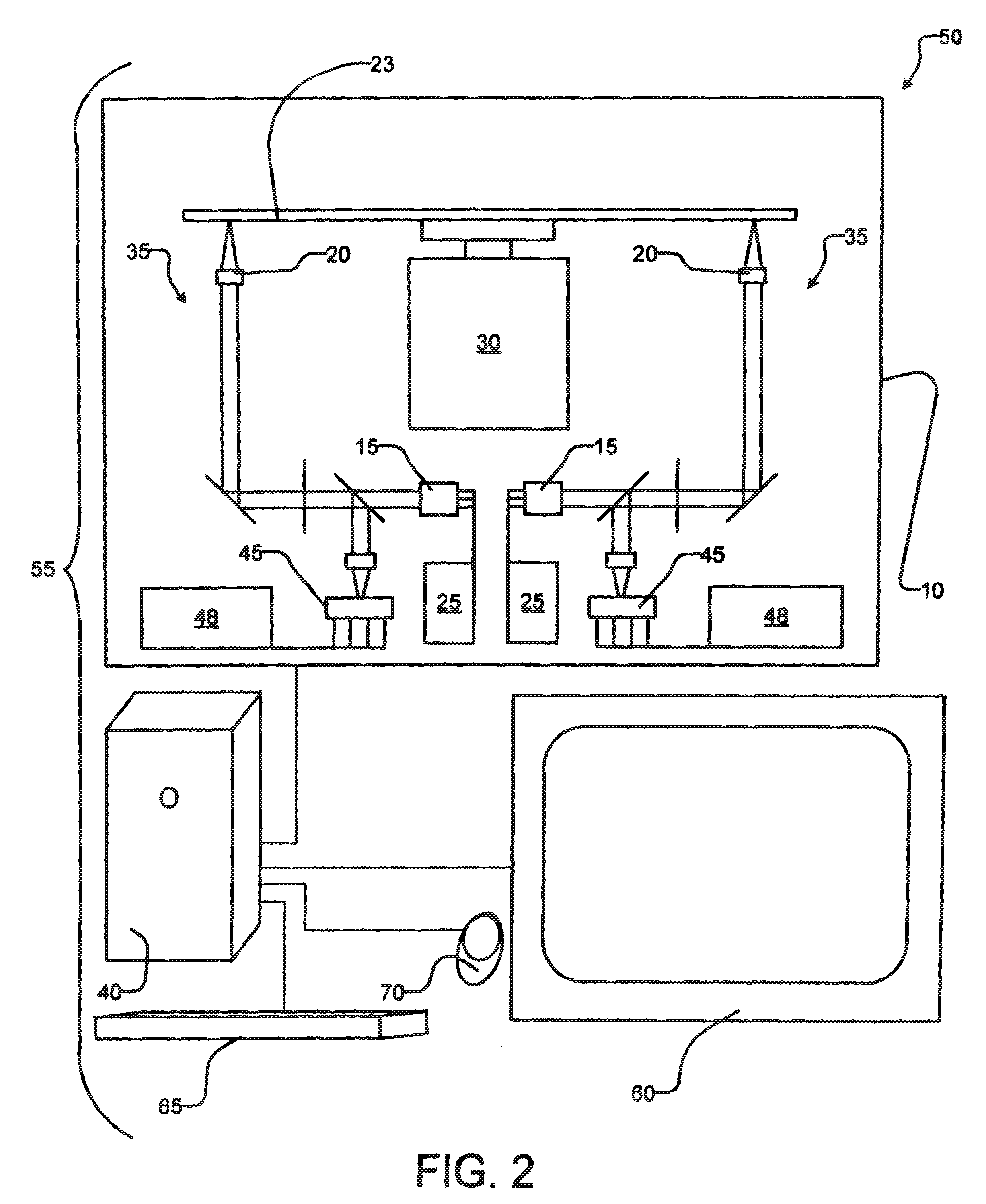
[0066]A commercially available DVD disc drive from Toshiba America, Inc. (New York, N.Y.) would be obtained. The control electronics and read / write electronics would be modified appropriately. A custom-built optical pick up, integrating the read laser and high-power write laser to be obtained from Pulstec Industrial Co., Ltd. (Hamamatsu City, Japan), the optics (designed for this higher power), and the tracking and autofocusing positioning mechanisms would be installed in the drive housing. Programmable devices would be loaded with appropriate firmware for controlling all the preceding components. These steps would result in a working optical disc drive that delivers high power laser energy to the surface of an optical disc.
example 2
Using a High-Powered Disc Drive to Write to a Chromium Data Layer
[0067]A commercially available polycarbonate substrate having a conventional wobble groove was sputter coated with chromium to form a layer having a thickness in a range from about 10 nm to about 40 nm to form an unbonded optical disc. Digital data was written at a speed of DVD 1X to the disc by forming indelible marks of a variety of sizes in the chromium layer using a PULSTEC® ODU-1000. The marks were formed by delivering pulsed power within a range from about 90 mW to about 100 mW at the surface of the disc. The disc was then tracked and read in the ODU-1000, showing that such powers and such data materials can be used to form permanent readable data in optical disc media.
example 3
Using a High-Powered Disc Drive to Write to a Chromium Data Layer of a Bonded Optical Disc
[0068]Commercially available polycarbonate substrates were obtained. The base substrate, having a conventional wobble groove, was sputter coated with chromium to form a data layer having a thickness of about 20 nm. The dummy substrate was placed and bonded atop the data layer and the base substrate to form a bonded optical disc. Digital data was written at a speed of DVD 1X to the disc by forming indelible marks of a variety of sizes in the chromium layer using a PULSTEC® ODU-1000 delivering a pulsed laser power of about 31 mW at the surface of the optical disc. The optical disc was tracked and read with a modulation in a range between about 70% to about 75% and a bucket jitter of about 4.3 ns. The ODU-1000 was used to write to a substantially identical optical disc at DVD 4X with a pulsed power at the surface of the disc of 65 mW. Once again, the chromium data layer optical disc had a modulati...
PUM
 Abstract
Description
Claims
Application Information
 - R&D
- Intellectual Property
- Life Sciences
- Materials
- Tech Scout
- Unparalleled Data Quality
- Higher Quality Content
- 60% Fewer Hallucinations
Browse by: Latest US Patents, China's latest patents, Technical Efficacy Thesaurus, Application Domain, Technology Topic, Popular Technical Reports.
© 2025 PatSnap. All rights reserved.Legal|Privacy policy|Modern Slavery Act Transparency Statement|Sitemap|About US| Contact US: help@patsnap.com


