
Random number generating device

generating device technology, applied in the field of random number generating devices, can solve the problems of inability to achieve the necessary operation rate, difficult to select a pair of negative resistive elements for a random number generator, and the circuit has not been put into practice, so as to achieve the effect of reducing power consumption, high trueness, and easy setting of appropriate magnetization curren

Inactive Publication Date: 2010-05-27
NAT INST OF ADVANCED IND SCI & TECH
View PDF5 Cites 29 Cited by
  • Summary
  • Abstract
  • Description
  • Claims
  • Application Information

AI Technical Summary

Benefits of technology

[0050]The random number generating device according to the present invention is compact, achieves decreased consumption of power, and allows for high-rate action and retention of generated random numbers in a nonvolatile manner.
[0051]With the random number generating device according to the present invention, fluctuations of the magnetic free layer in the magnetoresistive element due to an external field are used as a seed of random numbers, so that binarized random numbers with high trueness can be generated at high rates without using large-scale amplifiers and threshold circuits and the resultant data can be retained in a nonvolatile manner.
[0052]Independently of the shape of the magnetoresistive element, appropriate magnetization current can be set with ease based on the characteristic that the inclination becomes moderate independently of the shape of the magnetoresistive element. Therefore, it is possible to reduce the size of the magnetoresistive element to less than 1 micrometer square and the random number generating device according to the present invention can be arrayed by using the existing integrated circuit technologies. In addition, the magnetoresistive element can be designed so as to use very low electricity such that the energy required to generate 1 bit of a random number is no greater than 1 nanojoules when a CPP-GMR element is used or no greater than 10 nanojoules when an MgO-TMR element is used. Further, judging from the rate (on the order of 1 nano second) of inversion of magnetization, a random number generating rate on the order of 100 megabits / second (by at least 1,000 times faster than conventionally) can be obtained.
[0053]According to the present invention, a random generating device can be realized, which is small in size, needs little electricity to work, and allows for generation of random numbers with high trueness at high rates and in a nonvolatile manner. By incorporating the random number generating device in IC cards, cellular phones, portable computers, and so on, systems with high security can be realized. Thus, the present invention provides enormous industrial merits.
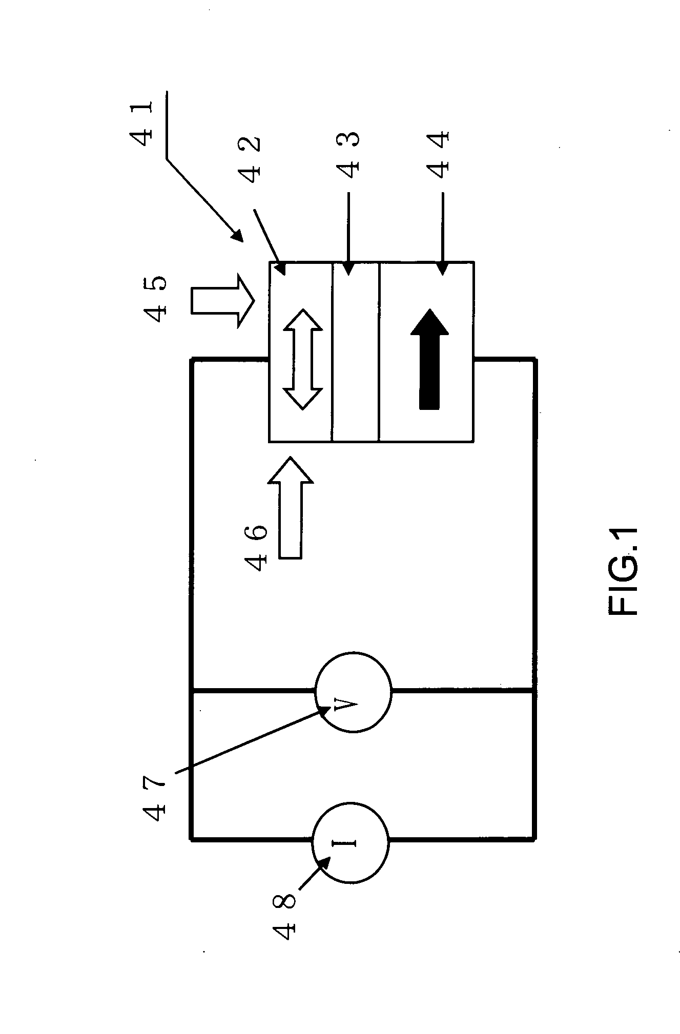
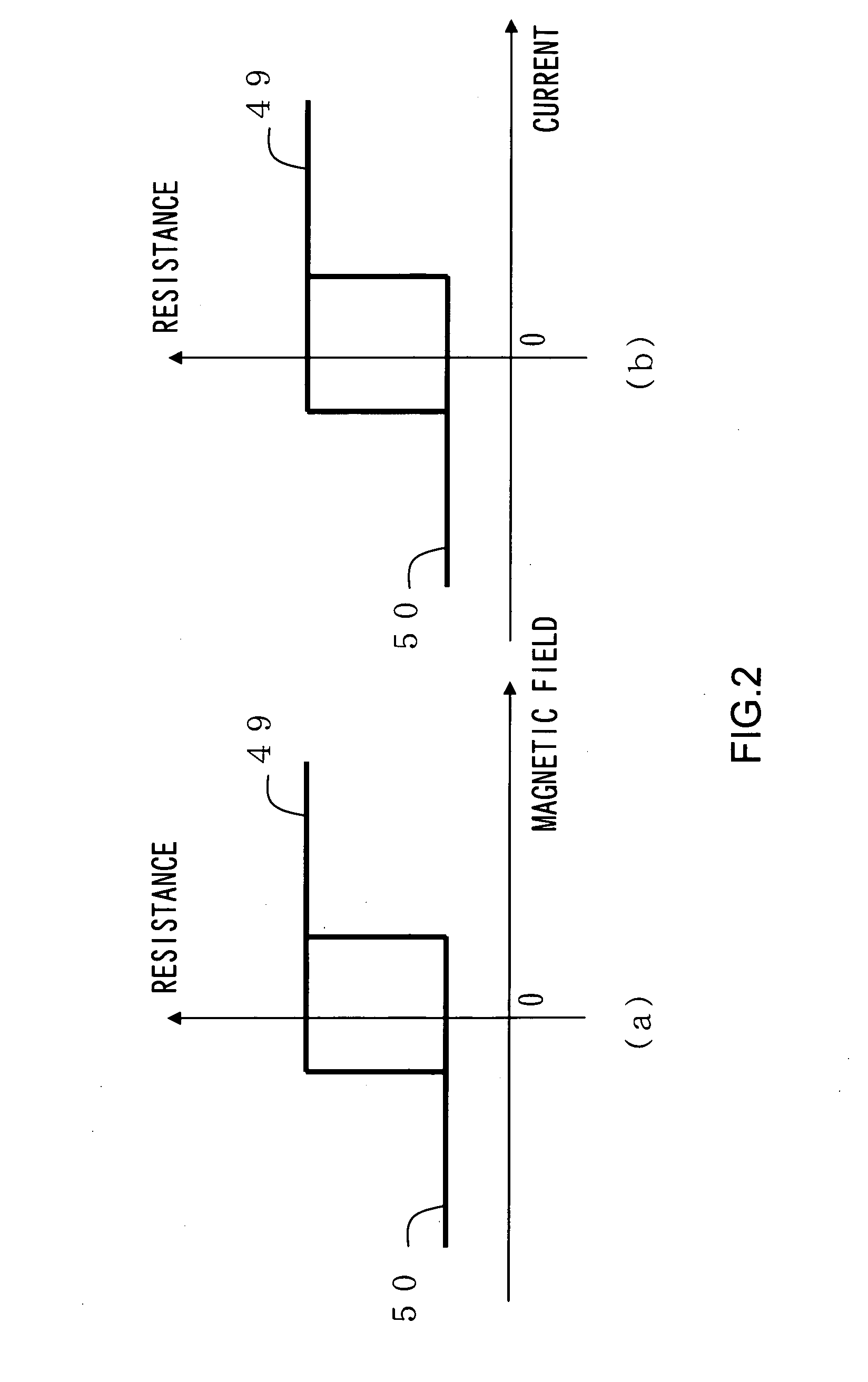
[0054]In a magnetoresistive element, the inversion of magnetization of the magnetization free layer is a probabilistic event and its probability varies depending on the magnitude of direct current and time during which this direct current is applied or on the magnitude of external magnetic field and time during which this external magnetic field is applied. In the present invention, binarized random numbers can be obtained in a nonvolatile manner without using large-scale amplifiers / threshold circuits by using fluctuations of the magnetic free layer in the magnetoresistive element due to an external field as a seed of random numbers, applying direct current or an external magnetic field to the magnetoresistive element such that the probability of inversion of the magnetization free layer is any desired value between 1 and 0 (preferably about 0.5), and then reading out resistance values of the element.
[0055]Since the size of the magnetoresistive element can be reduced to less than 1 micrometer square, it is easy to make an array of the elements by the existing integrated circuit technologies.

Problems solved by technology

However, they have a problem as follows.
Therefore, there arises a problem that it is difficult to achieve a necessary operation rate.
Therefore, there arises a problem that it is difficult to select a pair of negative resistive elements for a random number generator.
Such a circuit has not been put into practice yet.

Method used


Image

  • Random number generating device
  • Random number generating device
  • Random number generating device

Examples


first embodiment

[0076]Hereinafter, examples of random number generating devices according to embodiments according to the present invention are explained with reference to the attached drawings.

(Example in which a CPP-GMR Element is Used)

[0077]In an experiment of current injection magnetization inversion, for which as a magnetoresitive element a CPP-GMR element (i.e., an element having electrodes on upper and lower sides of a GMR (Giant Magneto Resistance) sensor film to allow current to flow perpendicularly to the film surface) is used, it is indicated that the probability of inversion of the magnetization free layer can be controlled.

[0078]FIG. 3 shows a construction diagram illustrating a CPP-GMR element used in this experiment.

[0079]A CPP-GMR element 10 shown in FIG. 3 has a construction that includes a substrate 11 having laminated thereon in order a buffer layer 12, an antiferromagnetic layer 13, a magnetization fixed layer 14, which is a 2.5-nm-thick Co—Fe layer, an interlayer 15, which is a...

second embodiment

[0095](Example in which MgO-TMR Element is Used)

[0096]In 2004, Yuasa, Parkin et al. found that a tunnel magnetoresistive element (MgO-TMR element) having an interlayer composed of crystalline magnesium oxide exhibits giant tunneling magnetoresistance (see Non-Patent Reference 4 (Experiment on a tunneling magnetoresistive element having giant magnetoresistance with an MgO barrier layer)). Thereafter, extensive research has been made on giant tunneling magnetoresistance in an MgO-TMR element. At present, it has become possible to obtain a magnetoresistance ratio of from several tens percents (%) to hundred and several tens percents (%) even in a low resistance region (i.e., region in which the sheet resistance value is on the range of several Ωμm2.

[0097]In such a low resistance MgO-TMR element, current injection magnetization inversion is possible. By using a low resistance MgO-TMR element in the random number generating device according to the present invention, an output of random n...

third embodiment

[0111](Example of High-Rate Action, Integration, and Low Power Consumption)

[0112]The rate of current injection magnetization inversion is very high and it has been reported based on the experiment using a CPP-GMR element (see, Non-Patent Document 5 (i.e., experiment that indicates that the current injection magnetization inversion in the CPP-GMR element takes place in about 200 ps) that magnetization inversion occurs using current pulses of several hundreds picoseconds width. Therefore, employing the current pulses of 1 ns to 10 ns width for resetting current and setting current, the random number generating device according to the present invention can be operated. In this condition, the generation rate of random numbers is estimated to become around 100 megabits / second. This rate is 1,000 times the generation rate of random numbers so far reported (see Non-Patent Reference 2).

[0113]Since the current injection magnetization inversion type magnetoresistive element may be fabricated ...


PUM


Abstract

A random number generating device is constructed such that it has improved random number generation rate and allows for construction of compact circuit with ease.The random number generating device includes a magnetoresistive element that has three layers consisting of a magnetization free layer, an interlayer, and a magnetization fixed layer, and has at least two resistance values depending on arrangement of magnetization in the magnetization free layer and the magnetization fixed layer, wherein the magnetoresistive element is subjected to be applied with a magnetization current so that the inversion probability of the magnetization free layer assumes a value between 0 and 1, through which the resistance value of the magnetoresistive element is extracted as random numbers.

Description

TECHNICAL FIELD[0001]The present invention relates to a random number generating device. More particularly, the present invention relates to a random number generating device that is small in size, needs little electricity to work, allows for easy integration, and also allows generated data to be retained in a nonvolatile manner.BACKGROUND ART[0002]Conventional methods for obtaining random numbers include a method in which pseudo random numbers are employed and a method in which natural random numbers are employed. The pseudo random numbers are obtained by generating random numbers using a predetermined program while natural random numbers are obtained by generating random numbers utilizing a probability event that occurs in nature. The probability event (a seed of natural random numbers) that can be used includes, for example, thermal noise (Johnson noise) in a resistor. The obtained thermal noise is amplified and compared with a predetermined threshold to obtain binarized random n...

Claims


Application Information

Patent Timeline
IPC IPC(8): G06F7/58
CPCG06F7/588
Inventor FUKUSHIMA, AKIOKUBOTA, HITOSHIYAKUSHIJI, KAYYUASA, SHINJIANDO, KOJI
Owner NAT INST OF ADVANCED IND SCI & TECH
Learn More