
Method and Apparatus for Providing LED Package with Controlled Color Temperature

a technology of led package and color temperature, which is applied in the direction of lighting and heating apparatus, electric discharge tube/lamp manufacture, discharge tube luminescnet screen, etc., can solve the problems of complicated binning system, complexity and additional processing steps, and variations in the color temperature of fabricated led package. achieve the effect of illuminating visual ligh

Inactive Publication Date: 2010-05-27
BRIDGELUX INC
View PDF12 Cites 28 Cited by
  • Summary
  • Abstract
  • Description
  • Claims
  • Application Information

AI Technical Summary

Benefits of technology

The patent describes an optical device that can adjust the color of light after it is made. The device includes a solid state light emitter and a layer of phosphor. The phosphor layer converts the first light to a second light with a different color. The phosphor layer can be adjusted after it is made to change the color of the second light to match the color quality detected by a light detector. The technical effect of this invention is that it allows for precise control over the color of light after it is made, which can be useful in various applications such as lighting and display technology.

Problems solved by technology

A problem associated with a conventional LED fabrication technique for dispensing phosphor layers is that the fabrication process can create variations in physical dimension of each phosphor layer dispensed.
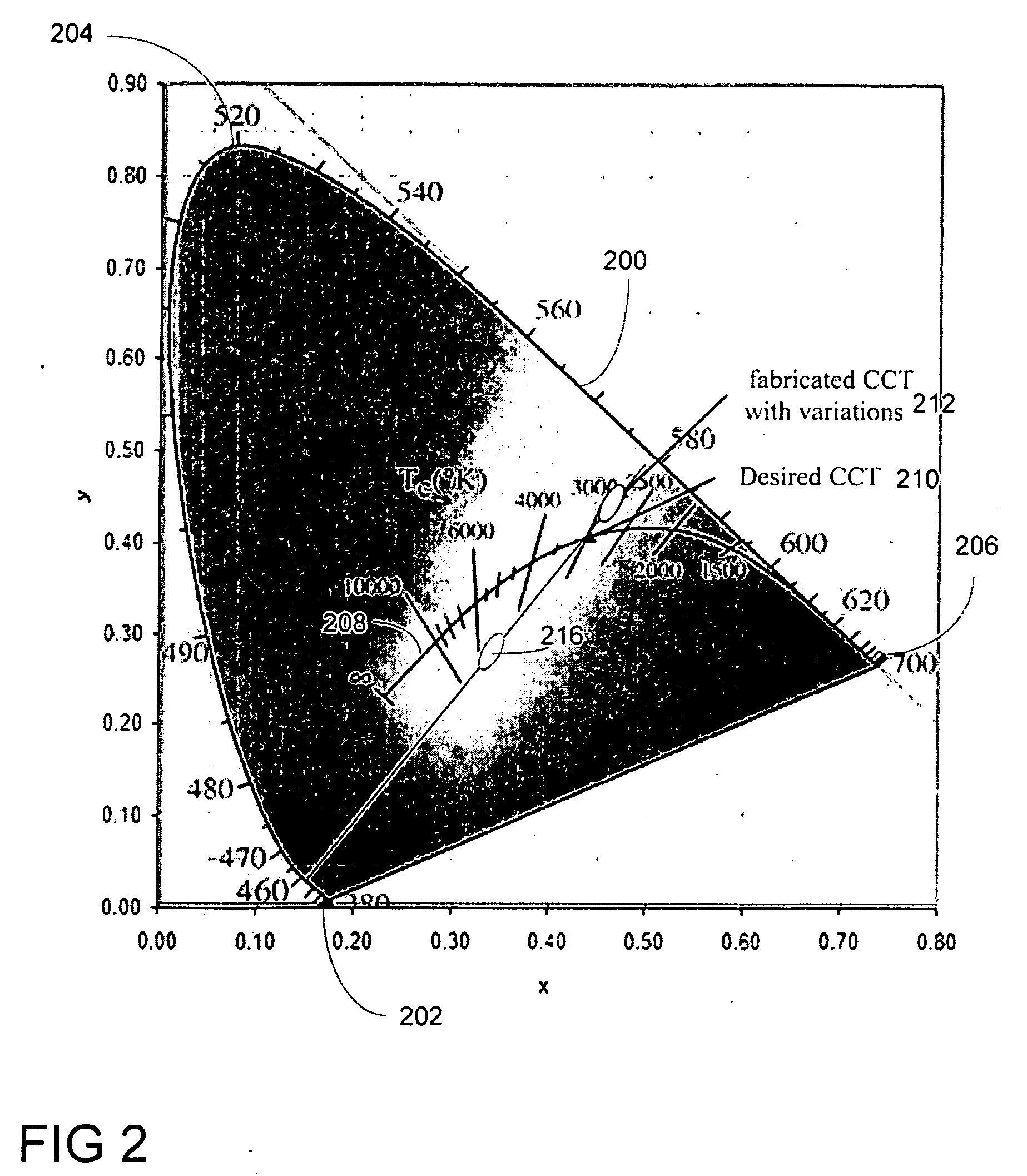
Variations in color temperature of fabricated LED packages complicate a binning system, which adds additional steps in an inventory system for sorting LED packages according to different color temperatures.
A drawback for this conventional approach, however, is complexity and additional processing steps.

Method used


Image

  • Method and Apparatus for Providing LED Package with Controlled Color Temperature
  • Method and Apparatus for Providing LED Package with Controlled Color Temperature
  • Method and Apparatus for Providing LED Package with Controlled Color Temperature

Examples


Embodiment Construction

[0017]Aspect(s) of the present invention is described herein in the context of a method, device, and apparatus of improving light color generated by an optical device with controlled color temperature.

[0018]Those of ordinary skills in the art will realize that the following detailed description of the exemplary aspect(s) is illustrative only and is not intended to be in any way limiting. Other aspects will readily suggest themselves to such skilled persons having the benefit of this disclosure. Reference will now be made in detail to implementations of the exemplary aspect(s) as illustrated in the accompanying drawings. The same reference indicators will be used throughout the drawings and the following detailed description to refer to the same or like parts.

[0019]In the interest of clarity, not all routine features of the implementations described herein are shown and described. It will, of course, be understood that in the development of any such actual implementation, numerous im...


PUM

PropertyMeasurementUnit
diameteraaaaaaaaaa
range of wavelengthsaaaaaaaaaa

Abstract

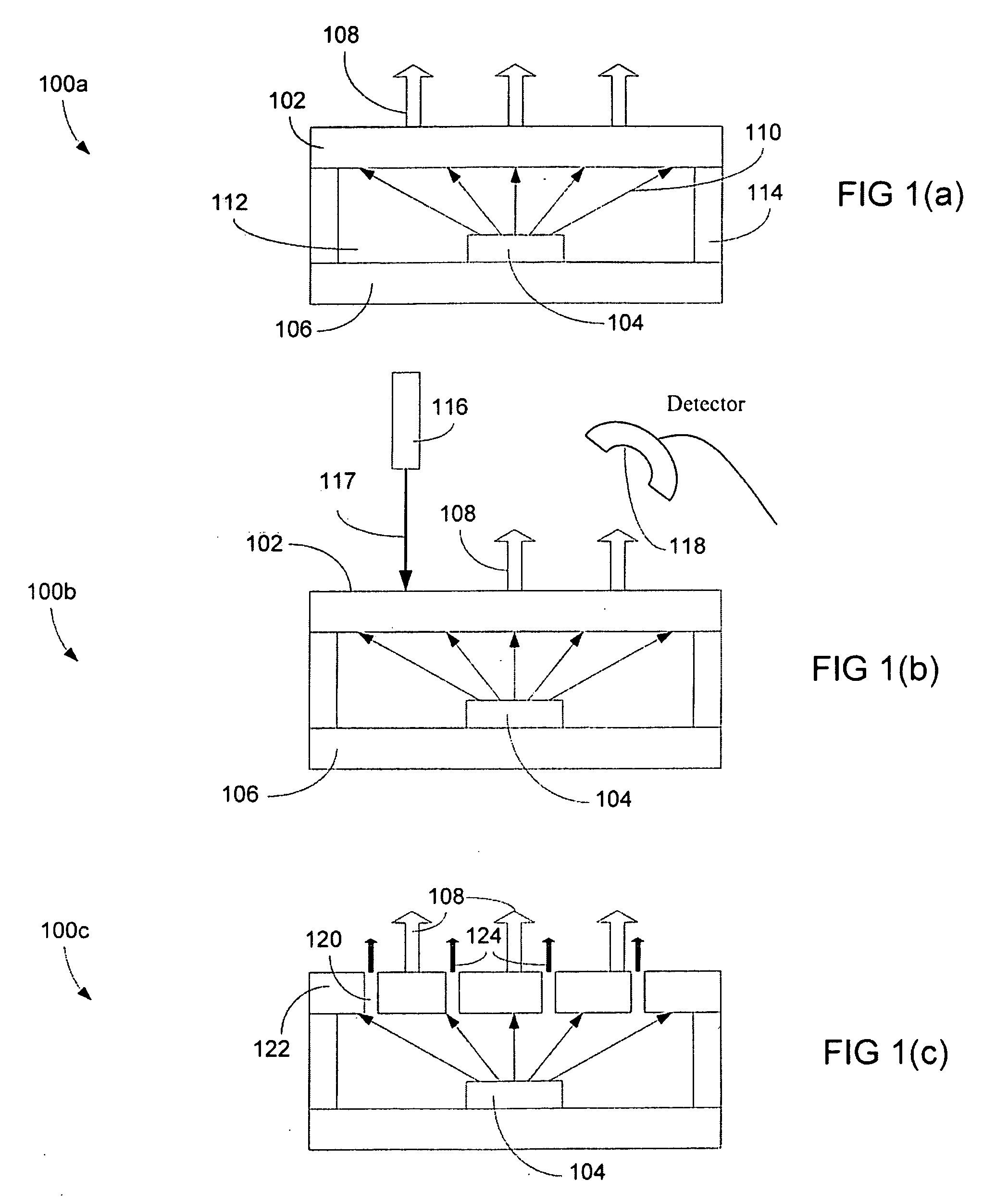
An optical device capable of illuminating visual light with adjusting color temperature after fabrication is disclosed. The optical device includes a solid state light emitter and a phosphor layer, which is formed over the solid state light emitter. The solid state light emitter, which can be a light emitter diode (“LED”), converts electrical energy to blue light. The phosphor layer subsequently converts first light with a first wavelength to second light with a second wavelength. In one example, the first light is blue light while the second light is white light. A portion of the phosphor layer is adjusted after the phosphor layer is formed for adjusting color of the white light in accordance with color quality of the light detected by a light detector.

Description

FIELD[0001]The exemplary aspect(s) of the present invention relates to lighting devices. More specifically, the aspect(s) of the present invention relates to solid state light emitting devices with adjustable color temperature.BACKGROUND[0002]A light emitting diode (“LED”) is a lighting semiconductor device capable of converting electrical energy to light. With recent improvements in luminous output from an LED, conventional lighting apparatus such as incandescent light bulbs and / or fluorescent lamps are likely to be replaced with LEDs in the foreseeable future. Various commercial applications of LEDs, such as traffic lights, automobile lightings, and electronic billboards, have already been placed in service.[0003]A conventional semiconductor package for an LED is typically fabricated with one or more phosphor layers and / or materials. The phosphor materials or layers are typically used to convert bluish radiation emitted from a semiconductor chip to brighter yellowish light with, f...

Claims


Application Information

Patent Timeline
Patent Type & Authority Applications(United States)
IPC IPC(8): H01J1/62H05B33/10
CPCY10T29/41H01L33/508
Inventor HELBING, RENE P.SHAIKEVITCH, ALEXANDER
Owner BRIDGELUX INC
Learn More