
Installation for recycling sanitary water

a technology for installing and recycling sanitary water, which is applied in the direction of water supply installation, water treatment parameter control, water/sludge/sewage treatment, etc. it can solve the problems of generating a large amount of noise and foam, difficult or even impossible access, and not recommended using a filter over the buffer tank, etc., and achieves the effect of convenient installation

Inactive Publication Date: 2010-05-27
BILLON MICHEL
View PDF16 Cites 19 Cited by
  • Summary
  • Abstract
  • Description
  • Claims
  • Application Information

AI Technical Summary

Benefits of technology

[0017]Another aim of the invention is to propose a solution that automatically maintains perfect hygiene of the sanitary installations and efficiently respects the environment.
[0018]Another aim of the invention is to provide a flushing system that is compatible with the above-mentioned installation and in particular with a high water column, this flushing system has to be at the same time reliable, robust and silent.
[0020]Yet another aim of the invention is to propose a sanitary unit for toilets that incorporates a water-saving system and that can easily be installed in any room of a home or premises of current dimensions without requiring major and expensive plumbing work.MAIN CHARACTERISTIC ELEMENTS OF THE INVENTION

Problems solved by technology

Moreover, using a filter over the buffer tank is not recommended.
In addition, the filter is positioned over the tank in a location hidden behind a decorative screen, making access difficult or even impossible.
At the outlet of the filter, the flow into the tank is free but has the disadvantage of generating a great deal of noise and foam.

Method used


Image

  • Installation for recycling sanitary water
  • Installation for recycling sanitary water
  • Installation for recycling sanitary water

Examples


Embodiment Construction

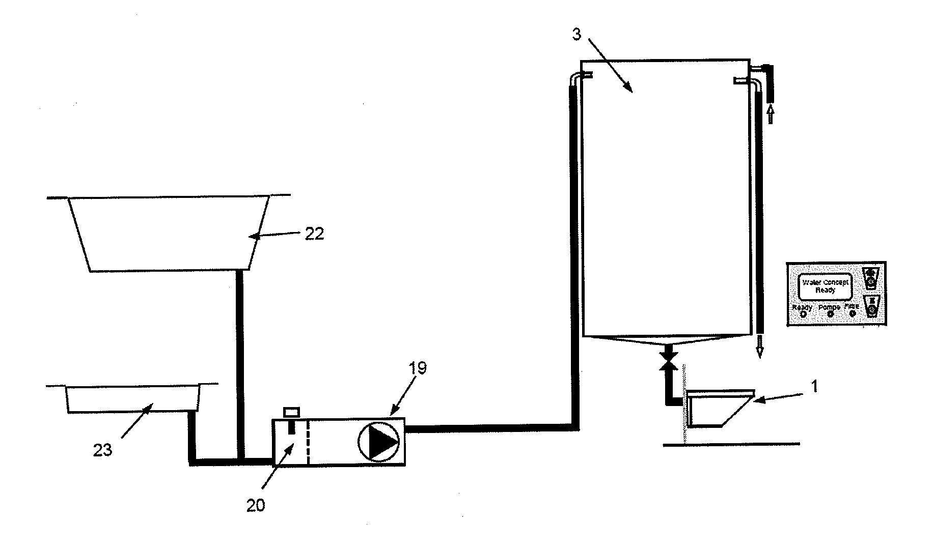
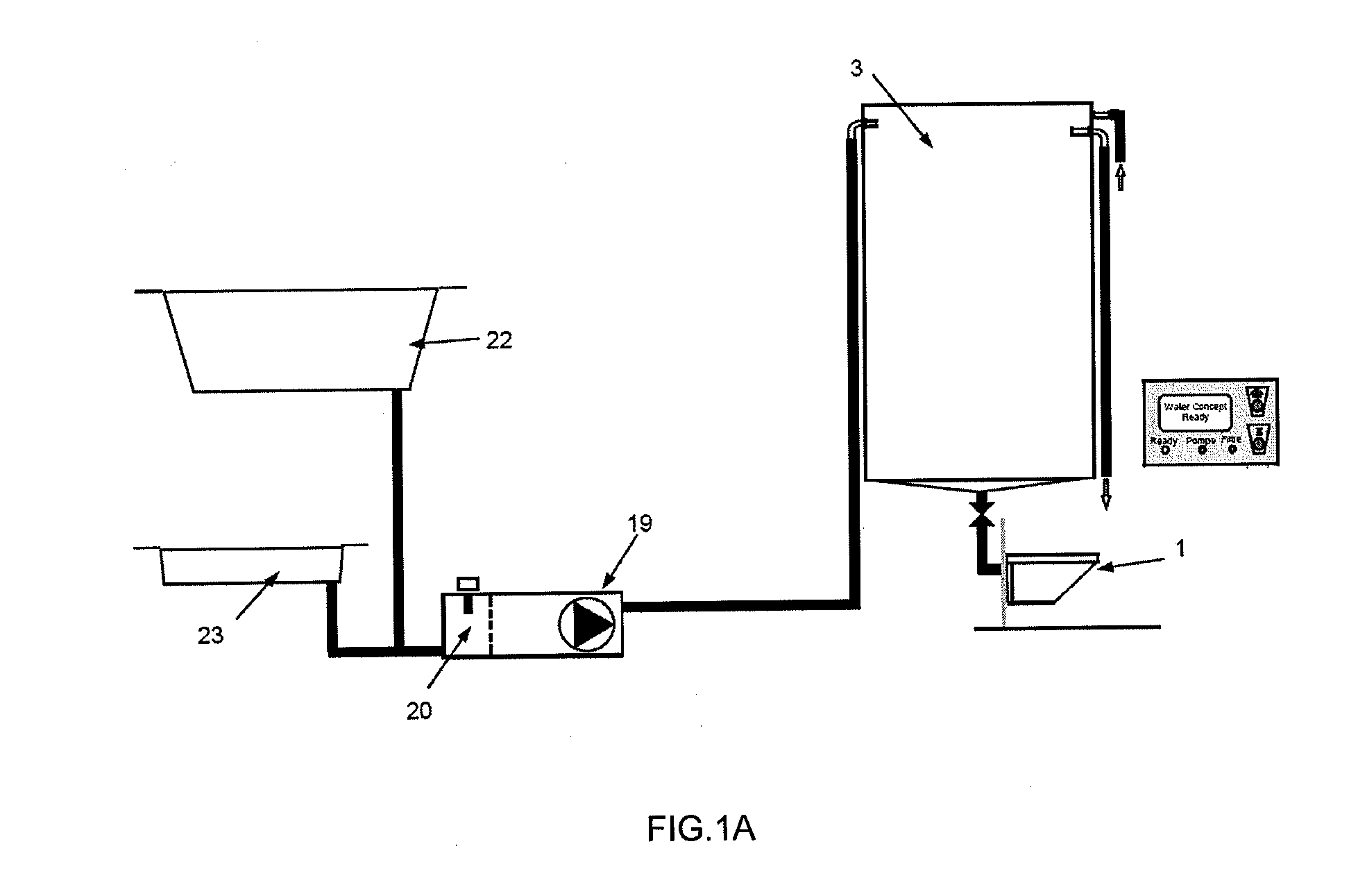
[0041]The invention is based on the recovery of the used water or “grey” water mainly coming from the bath, shower, washbasins, etc. in order to flush the home's toilet bowl(s).

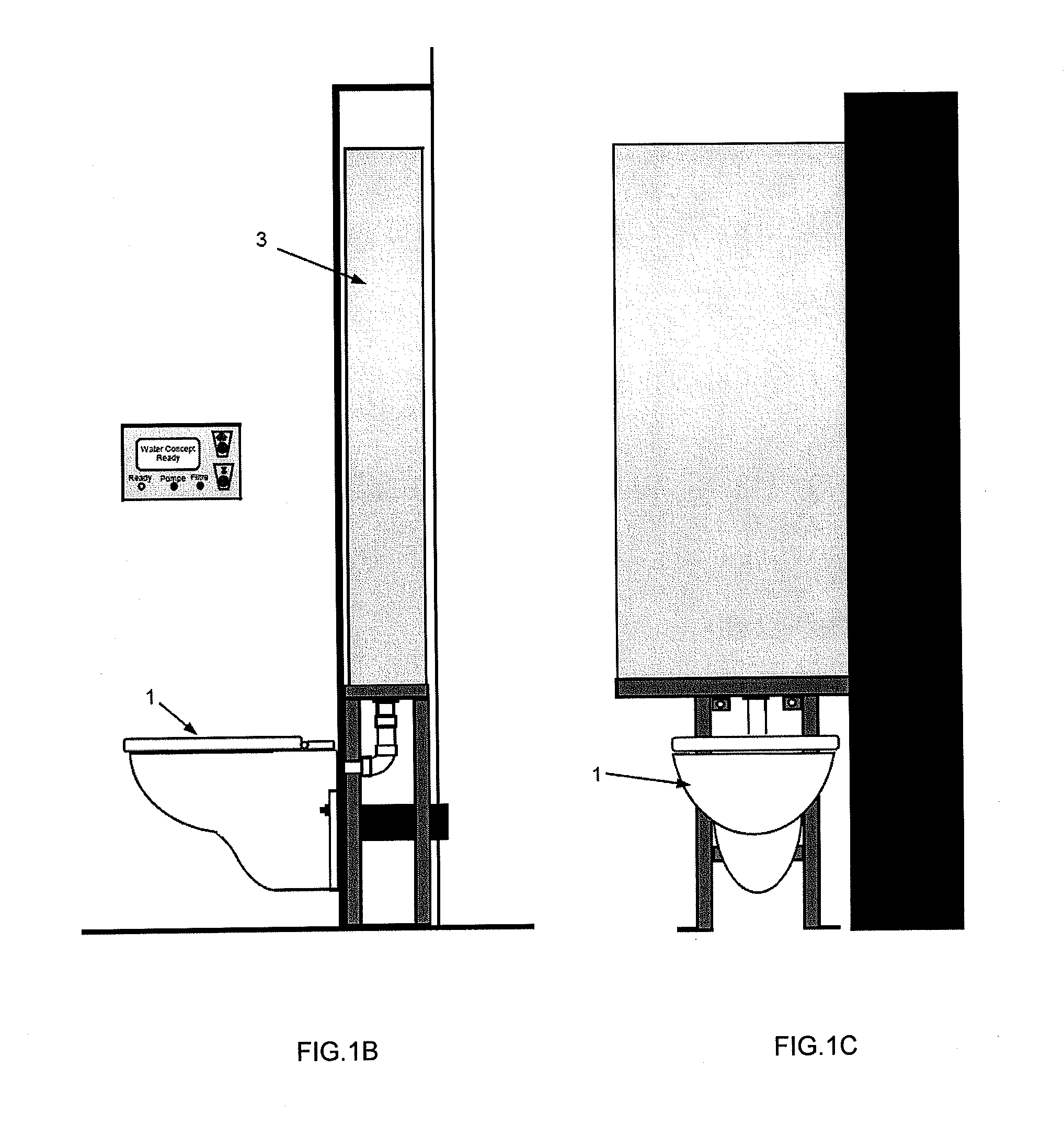
[0042]As shown in FIG. 1A to 1C, the system as in the invention is advantageously designed to be used with a wall-mounted toilet bowl 1.

[0043]Starting at the outlet of the bathtub 22 or shower 23, the drain pipe 21 coming from their traps enters a filter (FIGS. 3 and 4). This filter comprises a plastic housing (for example PVC, ABS, PE, etc.) of relatively small size (for example 150×250×165 mm), a filter cage 20 for coarse filtering (0.5-1 mm) and disposal of particles such as hair, a level probe 18 with a float and “reed” contact allowing to give the alert when the filter is clogged and needs cleaning, as well as an outlet towards the discharge (not shown) for overflow if a pump breaks down.

[0044]The product used for treating the grey water is of a solid type and is placed in the filter cage 20 where it pro...


PUM


Abstract

The present invention relates to an installation for recycling waste water coming from a sanitary equipment (22,23) and for reusing it to flush at least one toilet bowl (1), equipped with a system for saving flushing water fitted above the toilet and comprising a tank (3), a water-flushing mechanism (25A,24,17,14) positioned in the tank (3), a first pipe (21,7,15) to supply said waste water to the tank (3), a second pipe (13A) to supply running water to the tank, a filter (18,20) and a pump (19) positioned in the first pipe, a water-level sensor (11) and a controlled stop valve (13), wherein the flushing mechanism comprises a vertical-action drain valve (25A) positioned inside a flow-control tube (27) that extends over the entire height of the tank (3) and only connected to the rest of the tank (3) by one or more apertures (35) drilled in the side of said tube (27).

Description

FIELD OF THE INVENTION[0001]The present invention relates to an installation for recovering or recycling sanitary waste water from the baths, showers, sinks, etc. of a home and its reuse for flushing toilet bowls.STATE OF THE ART[0002]In homes, dwellings, hotels and more generally in any estate complex, the sanitary installations use a great volume of running water, generally drinkable, directly taken from the main supply network. In an urban environment, the volume of running water used and thus flushed down the drains amounts to millions of litres, of which almost 80% is used by sanitary installations and half of which in turn is used solely for flushing toilets. Thus, for example, each European uses 120 litres of drinking water every day. Of these 120 litres, 40 litres are used to flush toilet bowls, i.e. the equivalent of 6 flushes max. This use of running water comes at a consumption cost that is higher and higher because of the purification costs imposed by ever stricter envir...

Claims


Application Information

Patent Timeline
Patent Type & Authority Applications(United States)
IPC IPC(8): E03D5/016
CPCC02F2103/002C02F2209/005C02F2209/42E03B1/04E03D5/006E03B2001/045E03B2001/047E03D5/003E03B1/042Y02A20/108Y02A20/148Y02A20/30
Inventor BILLON, MICHEL
Owner BILLON MICHEL
Learn More