In-vehicle power transmission device and driving system for vehicle
a technology of transmission device and driving system, which is applied in the direction of hybrid vehicles, gearing, electric propulsion mounting, etc., can solve the problems of difficult to bring a rotor, difficult to restart inefficient energy use of the internal combustion engine, so as to facilitate the rotation of the driven wheel and eliminate the loss of electric energy
- Summary
- Abstract
- Description
- Claims
- Application Information
AI Technical Summary
Benefits of technology
Problems solved by technology
Method used
Image
Examples
first embodiment
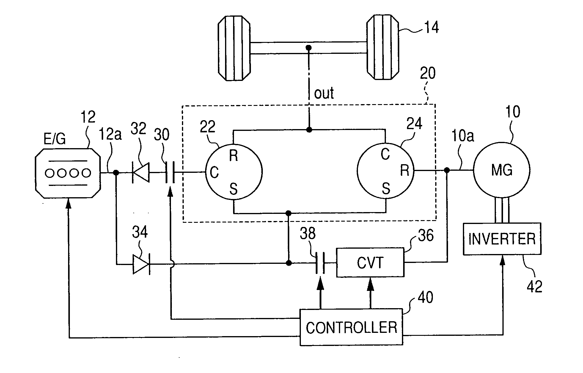
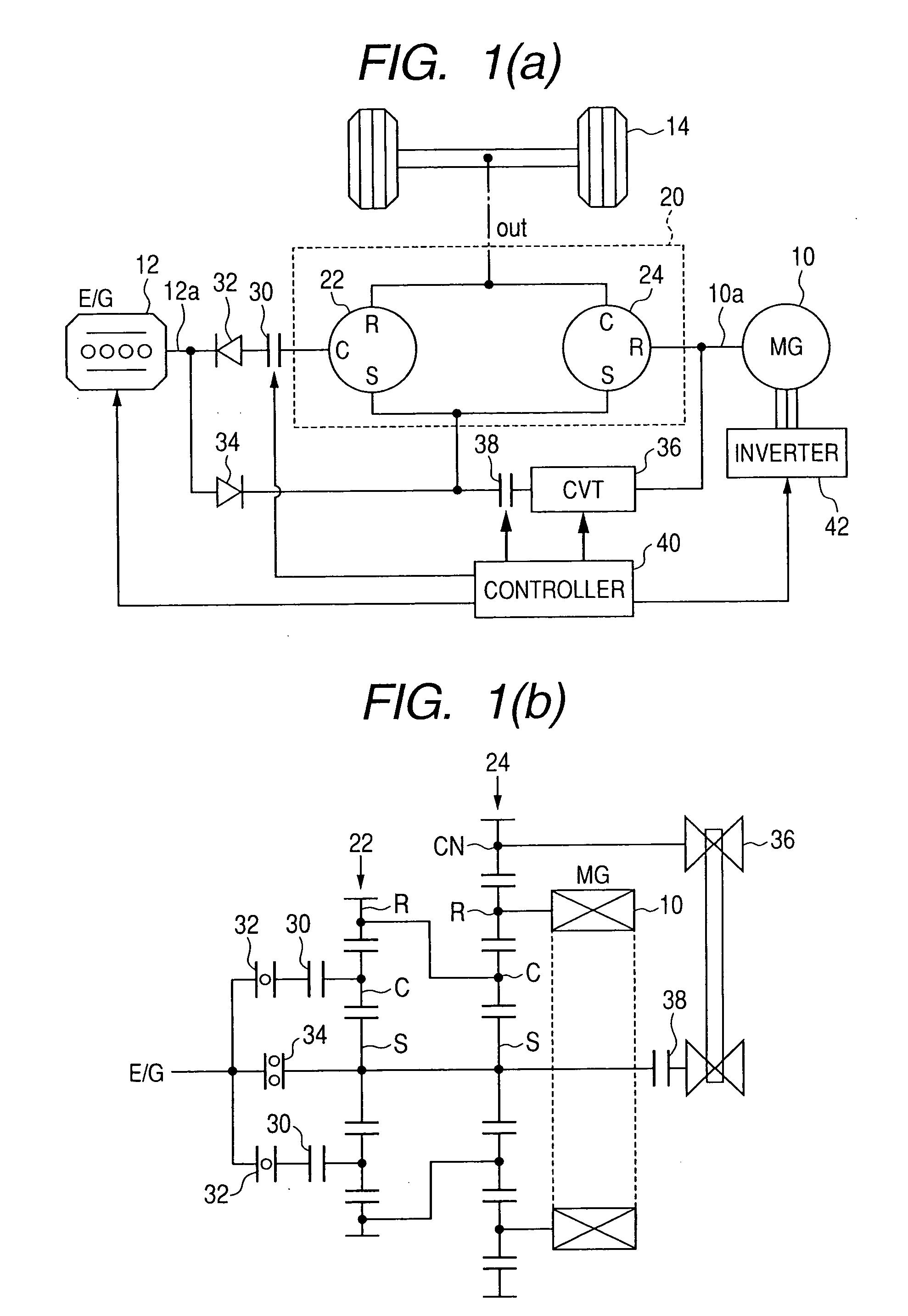
[0095]Referring to the drawings, wherein like reference numbers refer to like parts in several views, particularly to FIGS. 1(a) and 1(b), there is shown a hybrid system made up of an in-vehicle power transmission device and a driving system according to the invention. The in-vehicle power transmission device of this invention may alternatively be used with either an electric vehicle (EV) equipped only with an electric motor as a power source for running a road wheel or an automotive vehicle equipped only with an internal combustion engine as a power source for running a road wheel. The driving system is equipped with the in-vehicle power transmission device and a controller working to control an operation of the power transmission device. The driving system may also have installed therein a power source such as a motor-generator, an electric motor, or an internal combustion engine.
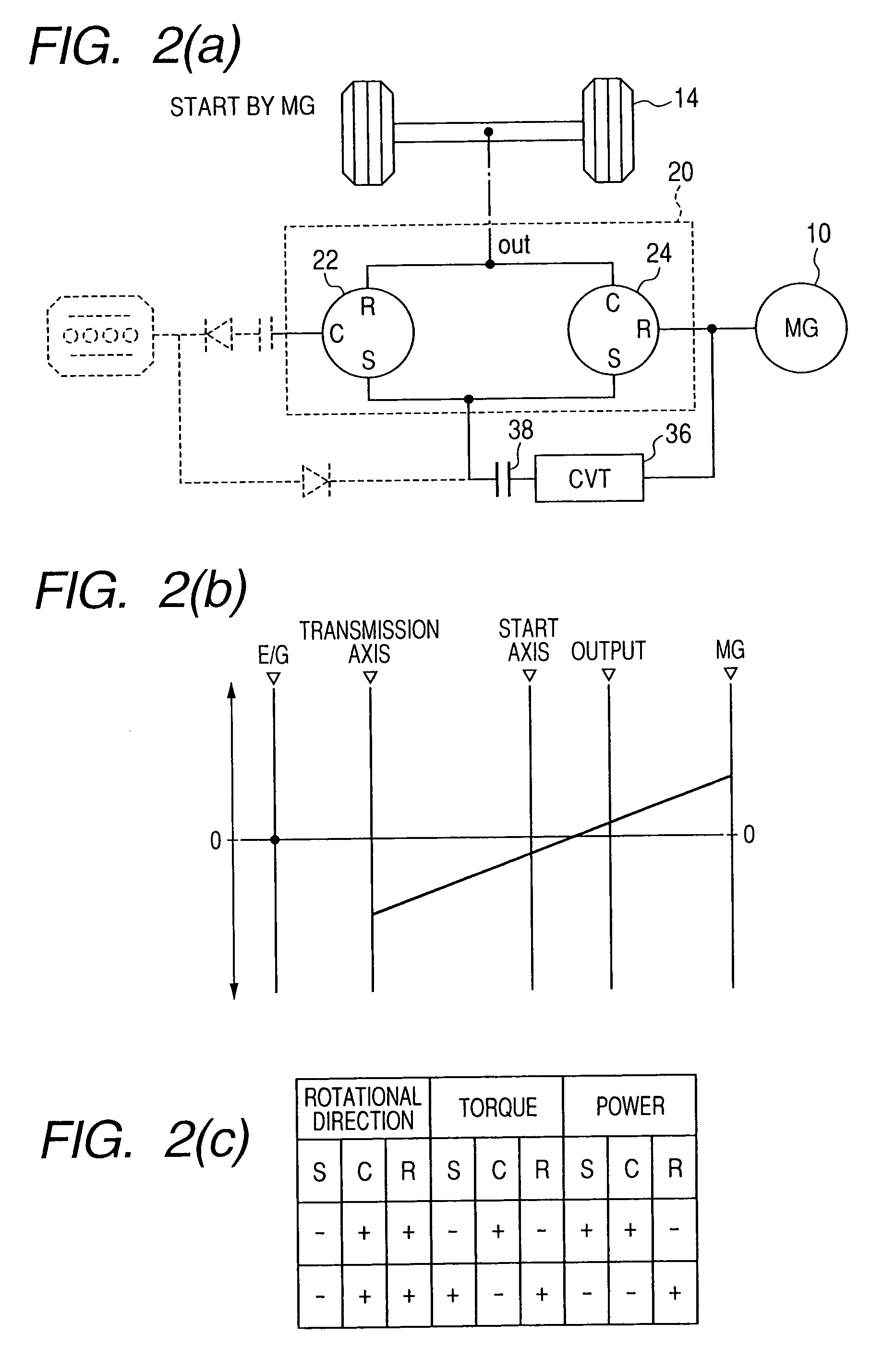
[0096]FIG. 1(a) illustrates the structure of the hybrid system. FIG. 1(b) is a skeleton view of power ...
second embodiment
[0121]FIG. 5 illustrates a hybrid system according to the invention. The same reference numbers as employed in FIG. 1 refer to the same parts, and explanation thereof in detail will be omitted here.
[0122]The hybrid system of this embodiment is designed to switch between the rotors of the power split device 20 which are to be connected mechanically to the driven wheels 14 of the vehicle. Specifically, the hybrid system, as clearly illustrated in FIG. 5, includes an electronically controlled clutch 50 which works as a switch or selector to select one of (a) a pair of the ring gear R of the first planetary gear set 22 and the carrier C of the second planetary gear set 24 and (b) the ring gear R of the second planetary gear set 24 which is to be coupled to the driven wheels 14.
[0123]The use of the clutch 50 enables the motor-generator 10 or the engine 12 to be run in an increased effective operation range. For example, increasing of the speed of the driven wheels 14 coupled to the ring ...
third embodiment
[0126]FIGS. 6(a) and 6(b) illustrate a hybrid system according to the invention. The same reference numbers as employed in FIG. 1 refer to the same parts, and explanation thereof in detail will be omitted here.
[0127]The power split device 20 has the first planetary gear set 22 connected mechanically at the carrier C thereof to the ring gear R of the second planetary gear set 24. The carrier C and the ring gear R work as engine starting rotors of the power split device 20 to provide the initial torque to the engine 12. The ring gear R of the first planetary gear set 22 is coupled mechanically to the carrier C of the second planetary gear set 24, which are in turn connected mechanically to the driven wheels 14. For the sake of simplicity of illustration, the driven wheels 14 are omitted from FIGS. 6(a) and 6(b). Instead, a path connected mechanically to the driven wheels 14 is expressed by “out”. The sun gear S of the first planetary gear set 22 is used as the rotor which is connected...
PUM
 Abstract
Description
Claims
Application Information
 - R&D
- Intellectual Property
- Life Sciences
- Materials
- Tech Scout
- Unparalleled Data Quality
- Higher Quality Content
- 60% Fewer Hallucinations
Browse by: Latest US Patents, China's latest patents, Technical Efficacy Thesaurus, Application Domain, Technology Topic, Popular Technical Reports.
© 2025 PatSnap. All rights reserved.Legal|Privacy policy|Modern Slavery Act Transparency Statement|Sitemap|About US| Contact US: help@patsnap.com


