
Image sensor and method for manufacturing the same

a technology of image sensor and manufacturing method, which is applied in the field of image sensor, can solve the problems of reducing the sensitivity of the output image, reducing the image quality, and reducing the charge sharing phenomenon, so as to reduce the charge sharing phenomenon and increase the fill factor

Inactive Publication Date: 2010-05-06
DONGBU HITEK CO LTD
View PDF8 Cites 1 Cited by
  • Summary
  • Abstract
  • Description
  • Claims
  • Application Information

AI Technical Summary

Benefits of technology

The patent text describes an image sensor and a method for manufacturing it that can increase the fill factor while minimizing charge sharing. It also reduces dark current and saturation reduction, and improves sensitivity by forming a smooth transfer path of photo charges between a photodiode and a readout circuit. The method also reduces etch damage of a contact and reduces dark current characteristics by removing an infinite current source. The image sensor includes a readout circuitry, an electrical junction region, a poly contact, an interconnection, and an image sensing device. The technical effects of the patent text are improved image quality and reduced noise in the image sensor.

Problems solved by technology

As the size of a photodiode is reduced for the purpose of increasing the number of pixels without increasing chip size, the area of a light receiving portion is also reduced, thereby resulting in a reduction in image quality.
According to a related-art image sensor, there is a limitation in that a charge sharing phenomenon may occur because both the source and the drain of the transfer transistor are heavily doped with N-type impurities.
The charge sharing phenomenon may cause reduction of the sensitivity of an output image and generation of image error.
Also, photo charges can not smoothly move between a photodiode and a readout circuitry, causing generation of a dark current and reduction of saturation and sensitivity.
That is, there is a cause of the generation of the dark current in the connection between an upper photodiode and a lower readout circuitry.
In addition to the generation of dark current, there are also many limitations in performing processes such as additional processes for reducing an etch damage and a contact resistance that may be generated in formation of a contact.

Method used


Image

  • Image sensor and method for manufacturing the same
  • Image sensor and method for manufacturing the same
  • Image sensor and method for manufacturing the same

Examples


Embodiment Construction

[0018]Hereinafter, embodiments of an image sensor and a method for manufacturing the same will be described with reference to the accompanying drawings.

[0019]In the description of embodiments, it will be understood that when a layer (or film) is referred to as being ‘on’ another layer or substrate, it can be directly on another layer or substrate, or intervening layers may also be present. Further, it will be understood that when a layer is referred to as being ‘under’ another layer, it can be directly under another layer, or one or more intervening layers may also be present. In addition, it will also be understood that when a layer is referred to as being ‘between’ two layers, it can be the only layer between the two layers, or one or more intervening layers may also be present.

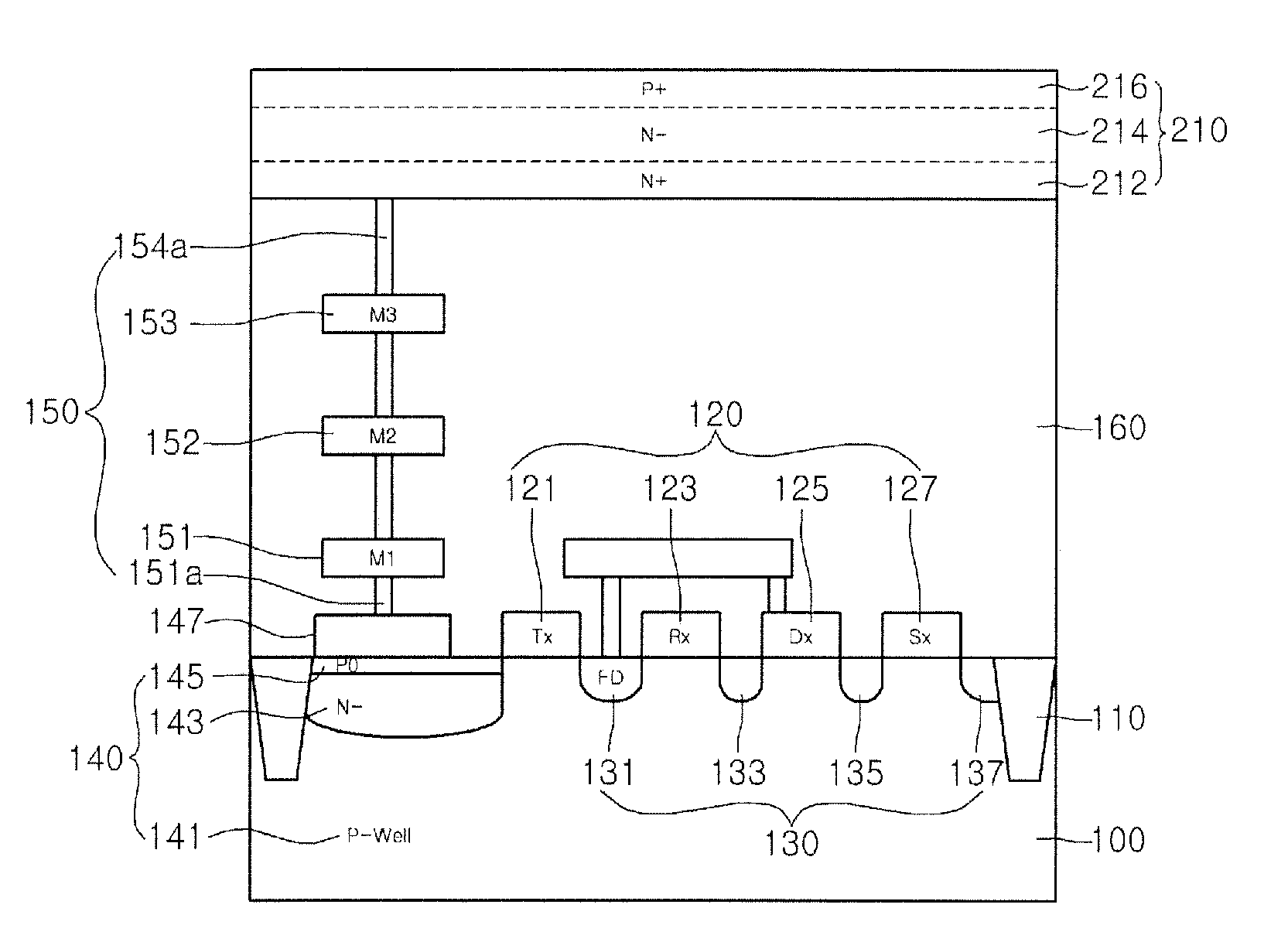
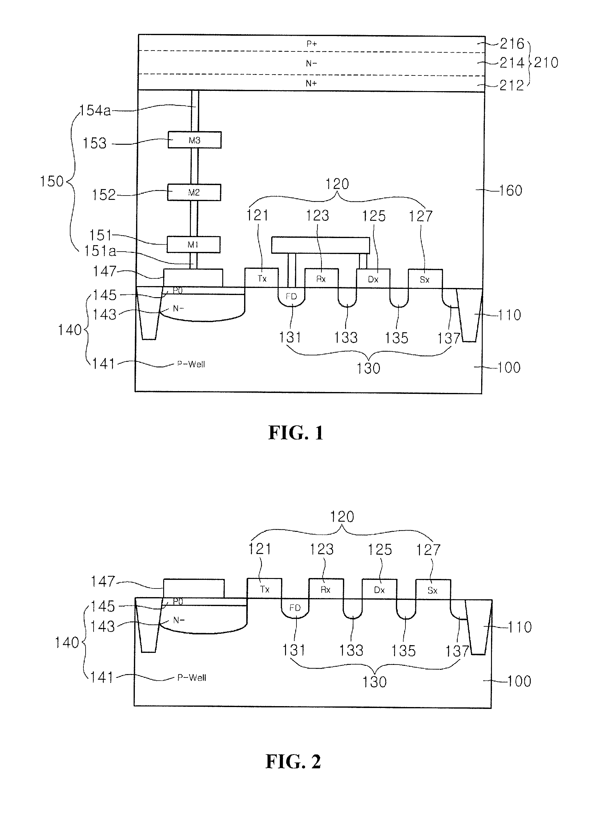
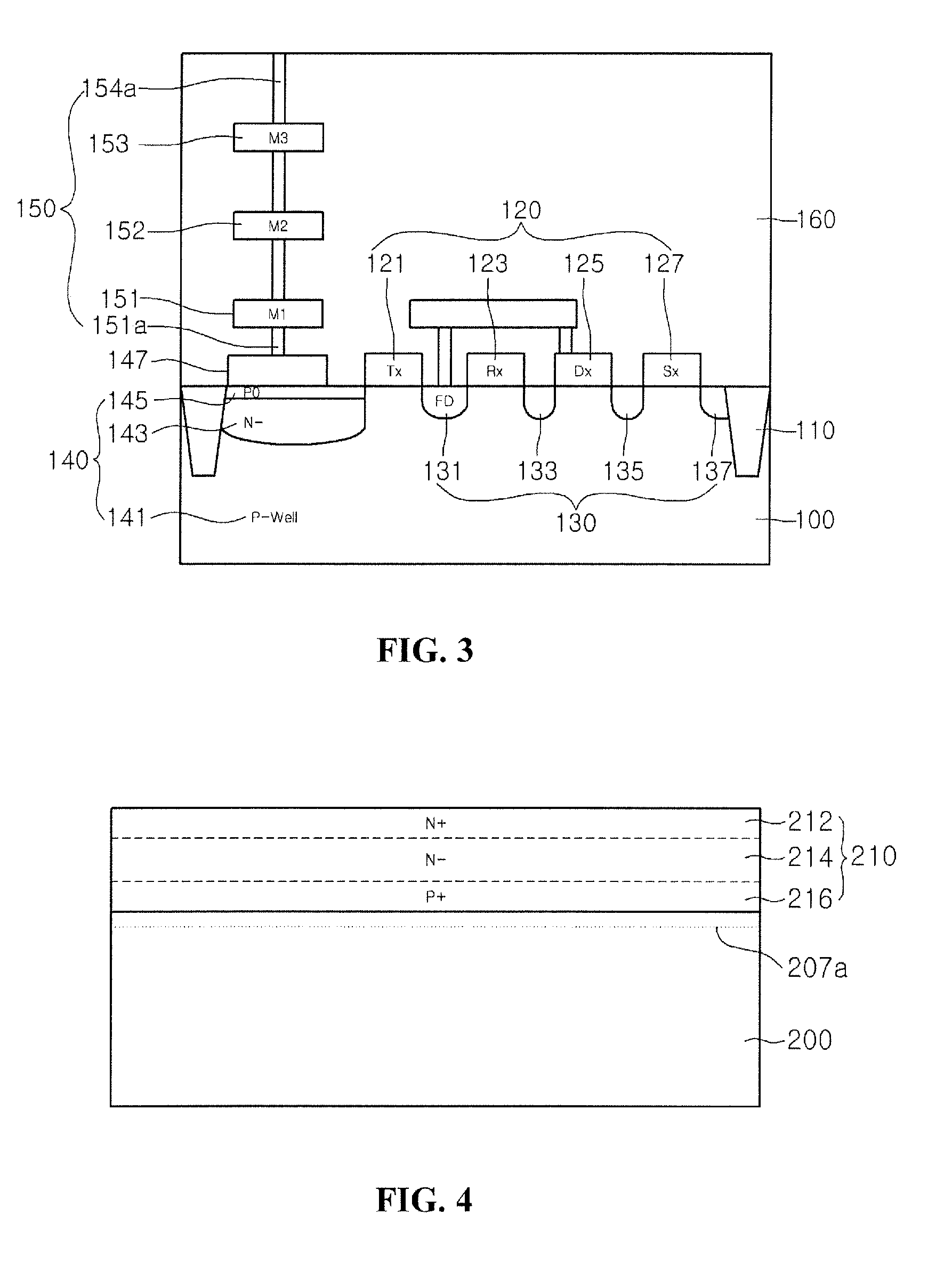
[0020]FIG. 1 is a cross-sectional view of an image sensor according to a first embodiment.

[0021]An image sensor according to a first embodiment can include: a readout circuitry 120 on a first substrate 100;...


PUM


Abstract

Provided are an image sensor and a method for manufacturing the same. The image sensor comprises a readout circuitry, an electrical junction region, a poly contact, an interconnection, and an image sensing device. The readout circuitry is formed on a first substrate. The electrical junction region is formed in the first substrate. The electrical junction region is electrically connected to the readout circuitry. The poly contact is formed on the electrical junction region. The interconnection is formed on the poly contact. The image sensing device is formed on the interconnection. The image sensing device is electrically connected to the readout circuitry through the interconnection, the poly contact, and the electrical junction region.

Description

CROSS-REFERENCE TO RELATED APPLICATION[0001]This application claims the benefit under 35 U.S.C. §119 of Korean Patent Application No. 10-2008-0109805, filed Nov. 6, 2008, which is hereby incorporated by reference in its entirety.BACKGROUND[0002]The present disclosure relates to an image sensor and a method for manufacturing the same.[0003]Image sensors are semiconductor devices which can convert optical images into electrical signals. Such image sensors can typically be classified as either charge coupled device (CCD) image sensors or complementary metal oxide semiconductor (CMOS) image sensors (CIS).[0004]During the fabrication of image sensors, a photodiode may be formed in a substrate using ion implantation. As the size of a photodiode is reduced for the purpose of increasing the number of pixels without increasing chip size, the area of a light receiving portion is also reduced, thereby resulting in a reduction in image quality.[0005]Also, since a stack height does not reduce as...

Claims


Application Information

Patent Timeline
Patent Type & Authority Applications(United States)
IPC IPC(8): H04N5/335H01L31/18H04N25/00
CPCH01L27/14632H01L27/14634H01L27/14636H04N5/369H01L27/146H01L27/148
Inventor HAN, CHANG HUN
Owner DONGBU HITEK CO LTD
Learn More