
Snowmobile Exhaust System

a technology of exhaust system and snowmobile, which is applied in the direction of vehicles, mechanical equipment, transportation and packaging, etc., can solve the problems of low noise of four-stroke engines, two-stroke engines generating noise at relatively high frequencies while in operation, and tuned pipes not well suited to provide noise reduction and performance control of four-stroke engines. , to achieve the effect of reducing engine nois

Active Publication Date: 2010-05-06
BOMBARDIER RECREATIONAL PROD INC
View PDF8 Cites 25 Cited by
  • Summary
  • Abstract
  • Description
  • Claims
  • Application Information

AI Technical Summary

Benefits of technology

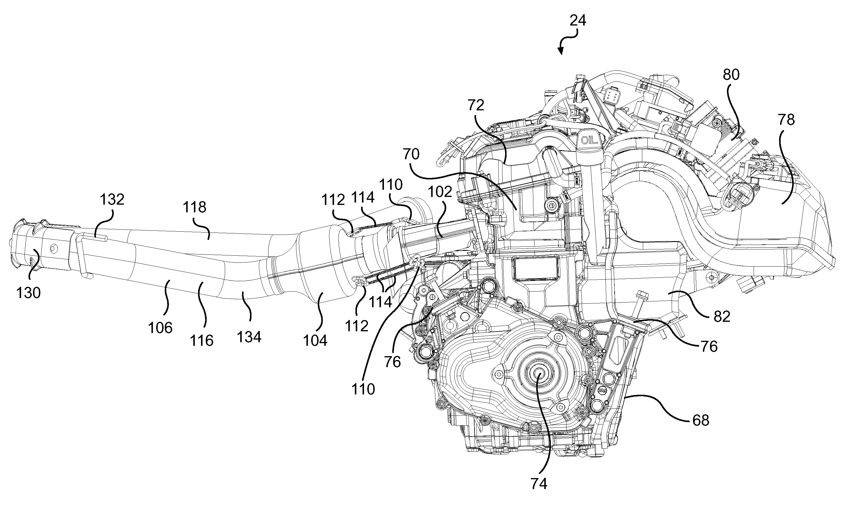
[0009]By providing an exhaust pipe routed as described above, the length of the exhaust pipe is sufficiently long to provide the desired noise reduction. Also, this permits the engine to be oriented with its exhaust ports facing forwardly, which reduces the amount of redesign and changes in layout of other components of the snowmobile. Finally, due to the relatively long length of the exhaust pipe, the exhaust gases are given more time to cool before entering the muffler. The acoustic waves travelling in cooler exhaust gases have a shorter wavelength for the same frequency, and acoustic waves with a shorter wavelength can be attenuated with a relatively simple muffler design (i.e. fewer internal chambers, smaller volume).
[0029]In a further aspect, the exhaust pipe reduces engine noise by at least 6 decibels.

Problems solved by technology

Two-stroke engines generate noise at relatively high frequencies while in operation.
While in operation, four-stroke engines generate noise at lower frequencies than two-stroke engines.
For this reason, and also due to the operation principle of four-stroke engines, tuned pipes are not well suited to provide noise reduction and performance control in four-stroke engines.
However, a larger muffler significantly increases the weight of the snowmobile, which negatively impacts the snowmobile's performance.
Also, since the muffler is usually disposed inside the front cowling of the snowmobile which provides only limited space which makes it difficult to accommodate a muffler having large dimensions.
However, since the exhaust ports of snowmobiles typically face towards a front of the snowmobile, the arrangement described in the '107 patent requires substantial redesign and changes in the lay-out of many of the components of the snowmobile, such as the tunnel.

Method used


Image

  • Snowmobile Exhaust System
  • Snowmobile Exhaust System
  • Snowmobile Exhaust System

Examples


Embodiment Construction

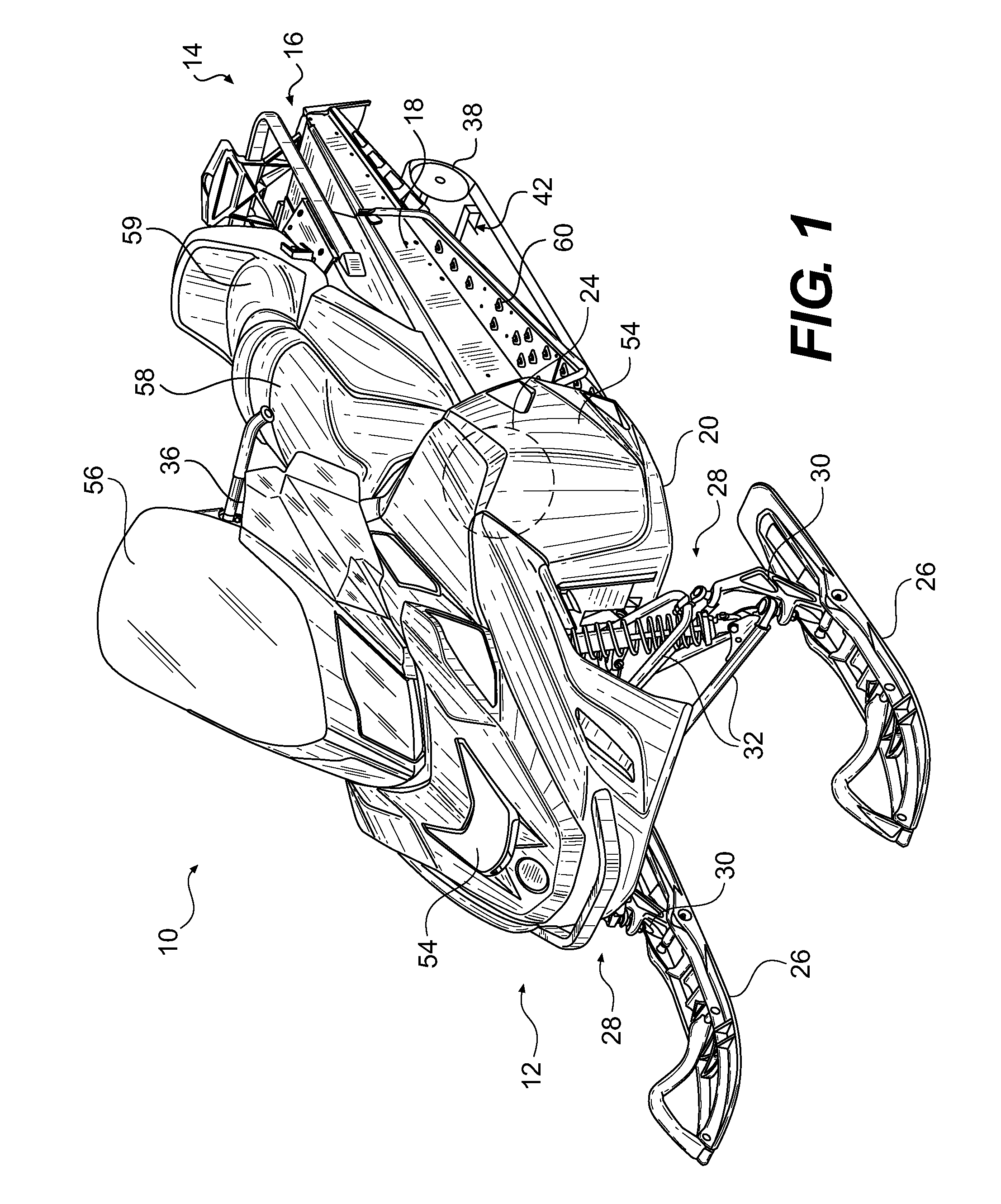
[0040]As shown in FIG. 1, a snowmobile 10, according to the present invention, includes a forward portion 12 and a rearward portion 14 which are defined consistently with a forward travel direction of the vehicle. The snowmobile 10 includes a frame (also known as a chassis) 16 which includes a rear tunnel 18, an engine cradle 20, and a sub-frame 22 (see FIGS. 2 and 3). An engine 24, which is schematically illustrated in FIG. 1, is carried by the engine cradle portion 20 of the frame 16 which forms part of an engine compartment. Two skis 26 are positioned at the forward portion 12 of the snowmobile 10 and are attached to the frame 16 through left and right front suspension assemblies 28. Each front suspension assembly 28 includes a ski leg 30, two A-arms 32 and ball joints (not shown) for operatively joining its ski leg 30 and A-arms 32. It is contemplated that other types of suspensions could be used. Each ski leg 30 is operatively connected to a steering assembly which includes a s...


PUM


Abstract

A snowmobile has a four-stroke engine mounted in an engine cradle and an exhaust system connected to the engine. The exhaust system includes a generally U-shaped exhaust pipe extending forwardly from the engine to a first point disposed forwardly of the engine cradle, and of suspension assemblies of the skis, and extending rearwardly from the first point to a second point disposed rearwardly of a front of the engine cradle.

Description

FIELD OF THE INVENTION[0001]The present invention relates to snowmobile exhaust systems.BACKGROUND OF THE INVENTION[0002]Many prior art snowmobiles are powered by engines operating on the two-stroke principle. Two-stroke engines generate noise at relatively high frequencies while in operation. In order to reduce the noise generated by two-stroke engines and to control the performance characteristics of these engines, snowmobiles powered by these engines have an exhaust system that includes a tuned pipe and a muffler.[0003]Recently, more snowmobiles are being powered by engines operating on the four-stroke principle. While in operation, four-stroke engines generate noise at lower frequencies than two-stroke engines. For this reason, and also due to the operation principle of four-stroke engines, tuned pipes are not well suited to provide noise reduction and performance control in four-stroke engines.[0004]Since tuned pipes cannot be efficiently used, one way of reducing the engine no...

Claims


Application Information

Patent Timeline
Patent Type & Authority Applications(United States)
IPC IPC(8): B60K13/04B62M27/02
CPCB60K13/04B60Y2200/252B62M27/02F01N3/08F01N2340/04F01N2470/20F01N2590/00
Inventor RICHER, MAX
Owner BOMBARDIER RECREATIONAL PROD INC
Learn More