
Cache memory and method of controlling the same

Inactive Publication Date: 2010-04-29
RENESAS ELECTRONICS CORP
View PDF4 Cites 12 Cited by
  • Summary
  • Abstract
  • Description
  • Claims
  • Application Information

AI Technical Summary

Benefits of technology

[0018]However, the present inventors have found that the processing in case of the miss hit of the patent document 2 may be improved. That is, according to the patent document 2, the WAIT signal is always output to the processor in case of the miss hit regardless of whether there is a subsequent memory access or not.
[0019]It is effective to stall the pipeline processing of the cache memory and to output the WAIT signal in case of the miss hit in order to maintain data consistency between the main memory and the cache memory when the subsequent memory access request corresponds to an access to the same memory block as the preceding memory access request in which the miss hit occurs. This is because, if the miss hit occurs in one memory access request and the tag memory is updated, and then it is possible to reflect the update result of the tag memory due to the occurrence of the miss hit in the preceding memory access request on the hit decision in the subsequent memory access request.
[0024]According to the cache memory and the method of controlling the same of the present invention as stated above, the output of the WAIT signal is controlled in accordance with the subsequent memory access in case of the miss hit. Accordingly, the pipeline processing of the processor is not stalled when the subsequent memory access does not influence the update processing of the data memory of the previous memory access, which enables to proceed the subsequent processing without delay.
[0025]According to the present invention, it is possible to provide a cache memory that enables to reduce the output of the WAIT signal to maintain the data consistency and to effectively process the successive memory accesses when there is no subsequent memory access in case of the miss hit, and a method of controlling the same.

Problems solved by technology

The number of pipeline stages of the cache memory is typically two because the increase of the cache access time is undesirable.
However, it is not always effective to stall the pipeline processing of the cache memory to output the WAIT signal when there is no subsequent memory access even when the miss hit occurs in one memory access request and updating of the tag memory is performed.

Method used


Image

  • Cache memory and method of controlling the same
  • Cache memory and method of controlling the same
  • Cache memory and method of controlling the same

Examples


first exemplary embodiment

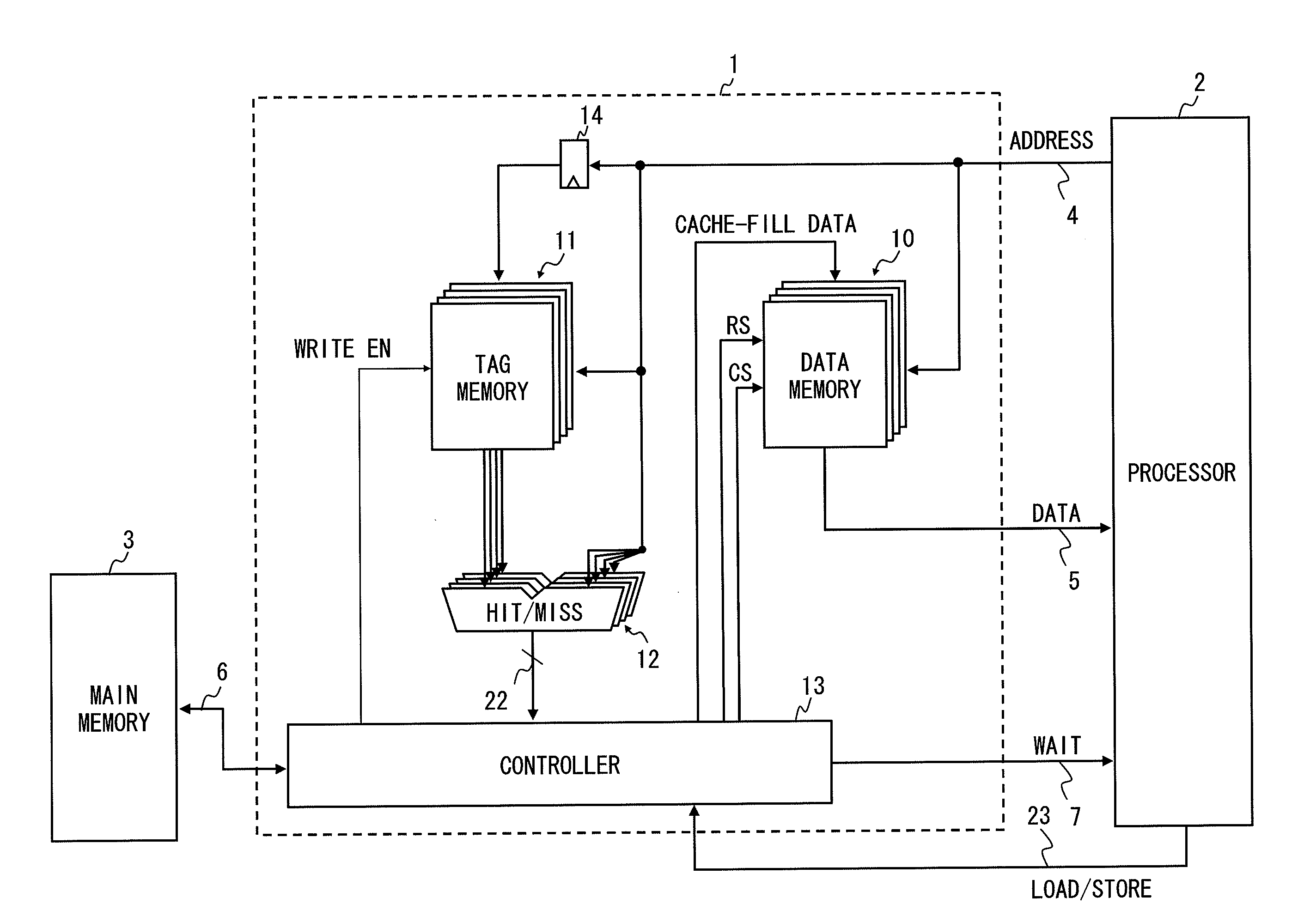
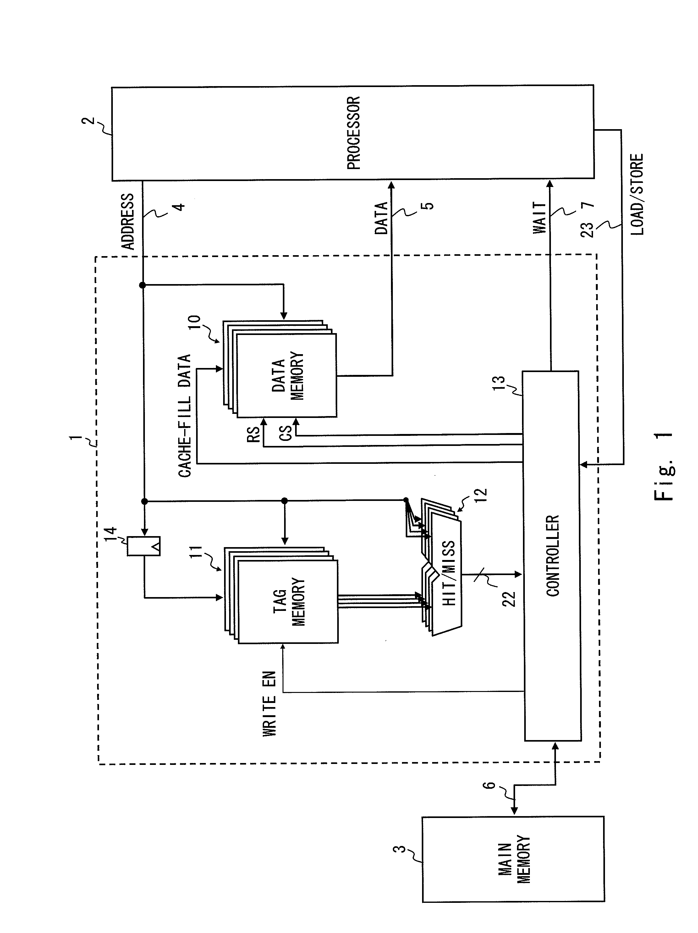
[0039]FIG. 1 is a configuration diagram of a cache memory according to the first exemplary embodiment of the present invention. A cache memory 1 according to the first exemplary embodiment of the present invention is a four-way set associative type cache memory. We assume that the cache memory here is the four-way set associative configuration so that the cache memory 1 and a cache memory 8 of a prior art shown in FIG. 8 are easily compared. However, such a configuration is merely one example. The number of ways of the cache memory 1 may be other than four or the cache memory 1 may be a direct-map type cache memory.

[0040]The components of a data memory 10, a tag memory 11, a hit decision unit 12, and a data latch 14, all of which being included in the cache memory 1, is the same as the components shown in FIG. 8. Therefore, the same components are denoted by the same reference symbols and detailed description will be omitted here.

[0041]The cache memory 1 is arranged between a proces...

second exemplary embodiment

[0059]A cache memory according to the second exemplary embodiment of the present invention is obtained by improving the patent document 2 by applying the present invention to the patent document 2. FIG. 4 is a configuration diagram of a cache memory 1a according to the second exemplary embodiment of the present invention. Although the cache memory 1a according to the second exemplary embodiment of the present invention has a four-way set associative configuration, it is not limited to this example as is similar to the first exemplary embodiment of the present invention. Further, the components shown in FIG. 4 which are disclosed in the patent document 2 or which are similar to those shown in FIG. 1 are denoted by the same reference symbols, and the detailed description thereof will be omitted.

[0060]In FIG. 4, there is added the control signal line 23 which is similar to that in FIG. 1 according to the first exemplary embodiment of the present invention compared with FIG. 11.

[0061]Fu...


PUM


Abstract

It is an object of the present invention to reduce output of a WAIT signal to maintain data consistency to effectively process subsequent memory access when there is no subsequent memory access in case of miss hit in a cache memory having a multi-stage pipeline structure. A cache memory according to the present invention performs update processing of a tag memory and a data memory and decides whether or not there is a subsequent memory access upon decision by a hit decision unit that an input address is a miss hit. Upon decision that there is a subsequent memory access, a controller outputs a WAIT signal to generate a pipeline stall for the pipeline processing of the processor to the processor, while the controller does not output a WAIT signal upon decision that there is no subsequent memory access.

Description

BACKGROUND[0001]1. Field of the Invention[0002]The present invention relates to a cache memory that processes a memory access from a processor by a pipeline which is divided into a plurality of process stages and a method of controlling the same.[0003]2. Description of Related Art[0004]A cache memory that uses a clock synchronous SRAM (synchronous SRAM) and adopts a pipeline structure has been put to practical use.[0005]A cache memory having such a pipeline structure is arranged between a processor and a low-speed memory and processes a memory access request from the processor by the pipeline which is divided into a plurality of process stages (see Japanese Unexamined Patent Application Publication No. 10-63575 (patent document 1), for example). The processor that performs a memory access request to the cache memory having the pipeline structure is typically a RISC (Reduced Instruction Set Computer) type microprocessor. The processor may be a CISC (Complex Instruction Set Computer) ...

Claims


Application Information

Patent Timeline
IPC IPC(8): G06F12/08G06F12/00
CPCG06F12/0855G06F12/0853
Inventor MIWA, HIDEYUKI
Owner RENESAS ELECTRONICS CORP
Learn More