
Liquid crystal display device

a display device and liquid crystal technology, applied in static indicating devices, instruments, non-linear optics, etc., can solve the problems of reducing affecting the display quality of liquid crystal display devices, etc., to suppress the increase in cost and improve display quality

Active Publication Date: 2010-04-29
SHARP KK
View PDF15 Cites 35 Cited by
  • Summary
  • Abstract
  • Description
  • Claims
  • Application Information

AI Technical Summary

Benefits of technology

[0099]The present invention provides a liquid crystal display device that realizes a three division structure without complicating the driver, thus contributing to improving the display quality (especially in terms of the viewing angle dependence of the γ characteristic) while suppressing the increase in cost.

Problems solved by technology

Although the display qualities of LCDs have been further improved nowadays, the problem of varying the γ characteristic with the viewing angle has arisen just recently.
This is a serious problem particularly when a still picture such as a photo is presented or when a TV program is displayed.
According to the IPS mode, however, it is more difficult to make panels that realize a high contrast ratio when the image on the screen is viewed straight with good productivity rather than in the MVA mode.
However, if the multi-pixel structure disclosed in Patent Document No. 3 is applied to either a high-definition LCD TV monitor or a large-screen LCD TV monitor, the following problem will arise.
Consequently, it becomes increasingly difficult (and expensive) to make a circuit for generating the oscillating voltage, the power dissipation will increase too much, or the influence of waveform blunting due to the electrical load impedance of the CS bus lines will be more and more significant.

Method used


Image

  • Liquid crystal display device
  • Liquid crystal display device
  • Liquid crystal display device

Examples


Embodiment Construction

[0169]Hereinafter, configurations for a liquid crystal display device as a preferred embodiment of the present invention and a TFT substrate for use in the device will be described with reference to the accompanying drawings. It should be noted that the present invention is in no way limited to specific preferred embodiments to be described below.

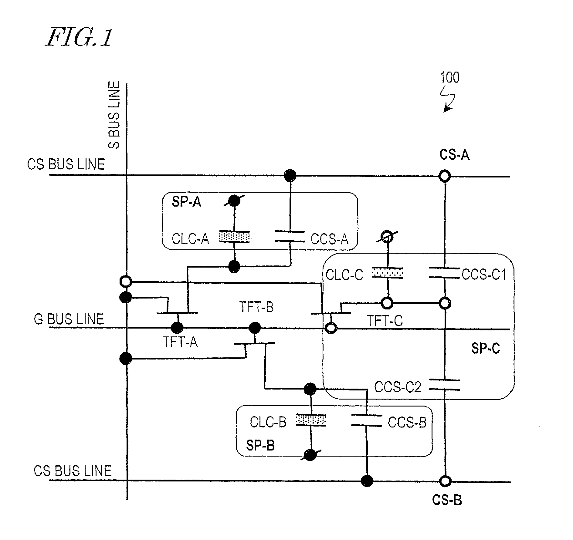
[0170]FIG. 1 schematically illustrates an equivalent circuit of one pixel of a liquid crystal display device 100 as a specific preferred embodiment of the present invention. Each pixel of the liquid crystal display device 100 includes three subpixels SP-A, SP-B and SP-C and is associated with three thin-film transistors TFT-A, TFT-B and TFT-C (for the three subpixels SP-A, SP-B and SP-C, respectively), one source bus line (S bus line), one gate bus line (G bus line) and two CS bus lines CS-A and CS-B.

[0171]Comparing the liquid crystal display device 100 to the equivalent circuit of the conventional liquid crystal display device 900 shown in...


PUM


Abstract

A liquid crystal display device according to the present invention includes: a plurality of pixels that are arranged in rows and columns so as to form a matrix pattern; and TFTs (TFT-A, TFT-B and TFT-C), source bus lines, gate bus lines and CS bus lines (CS-A and CS-B), which are associated with the respective pixels. Each pixel includes at least three subpixels (SP-A, SP-B and SP-C) with liquid crystal capacitors that are able to retain mutually different voltages. By supplying a signal (CS-A or CS-B) that makes two of the at least three subpixels display mutually different luminances at least at a certain grayscale tone from the source, gate and CS bus lines to each pixel, the at least three subpixels are able to display mutually different luminances.

Description

TECHNICAL FIELD[0001]The present invention relates to a liquid crystal display device and more particularly relates to a liquid crystal display device with a big screen that exhibits a wide viewing angle characteristic.BACKGROUND ART[0002]A liquid crystal display (LCD) is a flat-panel display that has a number of advantageous features including high resolution, drastically reduced thickness and weight, and low power dissipation. The LCD market has been rapidly expanding recently as a result of tremendous improvements in its display performance, significant increases in its productivity, and a noticeable rise in its cost effectiveness over competing technologies.[0003]Among other things, in-plane switching (IPS) mode LCDs (see Patent Document No. 1, for example) and multi-domain vertical aligned (MVA) mode LCDs (see Patent Document No. 2, for example) have been used as liquid crystal display devices with a wide viewing angle characteristic, of which the contrast ratio on the screen d...

Claims


Application Information

Patent Timeline
IPC IPC(8): G02F1/1343
CPCG02F2001/134345G09G3/3648G09G3/3659G09G2300/0443G02F1/136213G09G2300/0876G09G2320/0233G09G2320/028G09G2300/0447G02F1/134345
Inventor SHIMOSHIKIRYOH, FUMIKAZUTSUBATA, TOSHIHIDETAKEUCHI, MASANORIKITAYAMA, MASAEITSUMI, IKUMISHOHRAKU, AKIHIRO
Owner SHARP KK
Learn More