
Automatically connecting remote network equipment through a graphical user interface

a remote network and user interface technology, applied in the field of computer networking, can solve the problems of hardware that may behave unexpectedly and differently, difficult to identify and impossible to correct remotely, and tedious and error-prone process of network configuration

Active Publication Date: 2010-04-22
ACCENTURE GLOBAL SERVICES LTD
View PDF23 Cites 45 Cited by
  • Summary
  • Abstract
  • Description
  • Claims
  • Application Information

AI Technical Summary

Benefits of technology

[0012]This Summary is provided to introduce a selection of concepts in a simplified form that are further described below in the Detailed Description. This Summary is n

Problems solved by technology

Accordingly, a principle challenge in the field of computer networking is to design these multi-component, distributed systems to be able to efficiently and consistently exchange large amounts of data while effectively preventing unauthorized infiltration and limiting network failures.
However, configuring a network can be a tedious and error prone process.
Hardware may behave unexpectedly and differently than intended or designed.
Furthermore, each device in a network is typically locally configured, but as part of a network, any misconfiguration may have a global impact which can be difficult to identify and impossible to correct remotely.
Errors in configuration can result in packet (data) loss, additional latency, vulnerability to security breaches or even total network communication failure.
Accordingly, storage for the network component devices may require a considerable amount of space; likewise, a deployment of the test network may also require additional physical lab space.
Additionally, it may be difficult to remotely perform network design and testing from the inventory according to this technique.
For example, misconfigured devices may be inaccessible remotely.
Likewise, sharing equipment among distributed locations may be inconvenient and prohibitively impractical.
The cost of provisioning fully-functioning testing labs at discrete locations can be enormous.
Finally, since previously assembled configurations are not typically stored, test networks often require individual assembly, and physically setting up and reconfiguring a test environment for each and every test network can be inefficient and labor-intensive.
However, the behavior of the network devices along the transfer route (e.g., routers) may not always be consistent with the behavior of the devices in a traditional network (e.g., not a VPN).
For example, under typical router tunneling configurations, the routers comprising the network need to be specifically configured to allow for router tunneling, and thus may not be configured to transmit data without router tunneling.
Since local networks may not require router tunneling, the behavior of the router tested using router tunneling may be inconsistent with how the router will actual behave in practice.
Furthermore, other network devices may not support tunnels.
For example, firewalls and network servers typically do not support router tunneling.
Accordingly, a test network may be exceedingly difficult to simulate via router tunneling with any appreciable accuracy.
However, emulation of network devices cannot capture all aspects of a real network.
For example, configuration and simulated behavior is strictly limited to the simulation models according to the software, which may not be entirely comprehensive.
Often, this manifests as a limited number of available commands and a lack of comprehensive support.
These simulation models may not be available for some time after the release of a particular device, if at all.
This inconsistency may result in wasted time due to unnecessary or incorrect configuration.

Method used


Image

  • Automatically connecting remote network equipment through a graphical user interface
  • Automatically connecting remote network equipment through a graphical user interface
  • Automatically connecting remote network equipment through a graphical user interface

Examples


Embodiment Construction

[0029]Reference will now be made in detail to the preferred embodiments of the claimed subject matter, a method and system for the use of a reputation service provider, examples of which are illustrated in the accompanying drawings. While the claimed subject matter will be described in conjunction with the preferred embodiments, it will be understood that they are not intended to be limit to these embodiments. On the contrary, the claimed subject matter is intended to cover alternatives, modifications and equivalents, which may be included within the spirit and scope as defined by the appended claims.

[0030]Furthermore, in the following detailed descriptions of embodiments of the claimed subject matter, numerous specific details are set forth in order to provide a thorough understanding of the claimed subject matter. However, it will be recognized by one of ordinary skill in the art that the claimed subject matter may be practiced without these specific details. In other instances, w...


PUM


Abstract

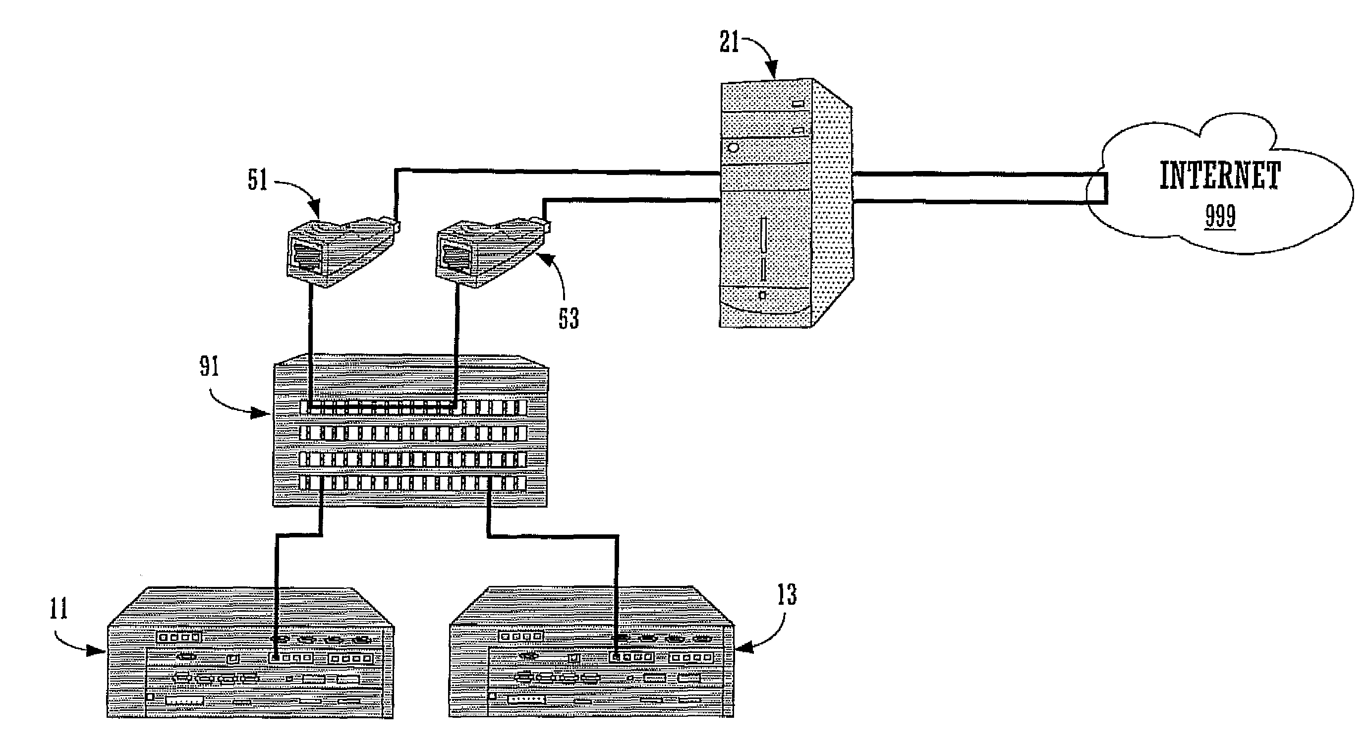
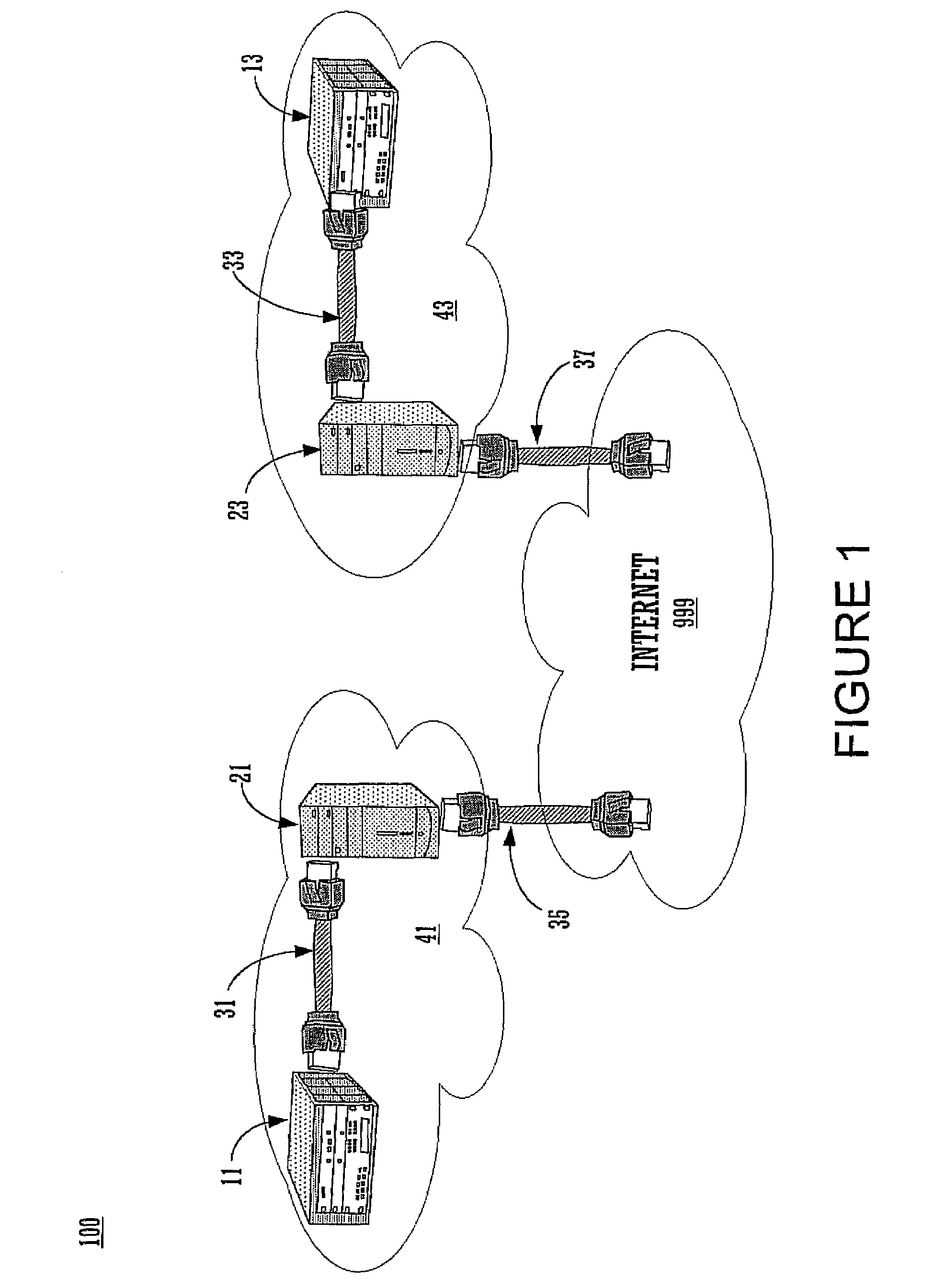
Embodiments of the present invention provide a method and system for designing a test network in an integrated application, and configuring remote network devices through a network design application to test a network design. One embodiment of the present claimed subject matter is provided as a system for automatically configuring remote network devices to simulate a network connection. The system includes a plurality of computing devices which are physically coupled to one or more network devices, wherein the network devices are automatically configured to comprise a test network corresponding to a remote test network topology design.

Description

BACKGROUND OF THE INVENTION[0001]Computer networks have become the dominant medium for the communication and exchange of data. The advent of the Internet in particular has spurred further developments in the field of computer networking. Today, larger computer networks can comprise robust, sophisticated systems capable of exchanging enormous amounts of data at impressive rates among a vast number of distributed computer systems.[0002]These larger computer networks may be implemented to include a variety of network components. Common network components (both hardware and software) are integrated to enhance the performance of the network, and to provide additional network functionality. These components may include dedicated servers that offer additional storage and processing capabilities; network routers that provide optimized packet routing and shared network access; and firewall software to provide network security. Often, each component must be individually configured to provide ...

Claims


Application Information

Patent Timeline
IPC IPC(8): G06F11/28
CPCH04L12/2697H04L41/0806H04L43/50H04L41/145H04L41/22H04L41/0856
Inventor LIU, HUANORBAN, DAN
Owner ACCENTURE GLOBAL SERVICES LTD
Learn More