Fuel injector with fuel pressure sensor
- Summary
- Abstract
- Description
- Claims
- Application Information
AI Technical Summary
Benefits of technology
Problems solved by technology
Method used
Image
Examples
second embodiment
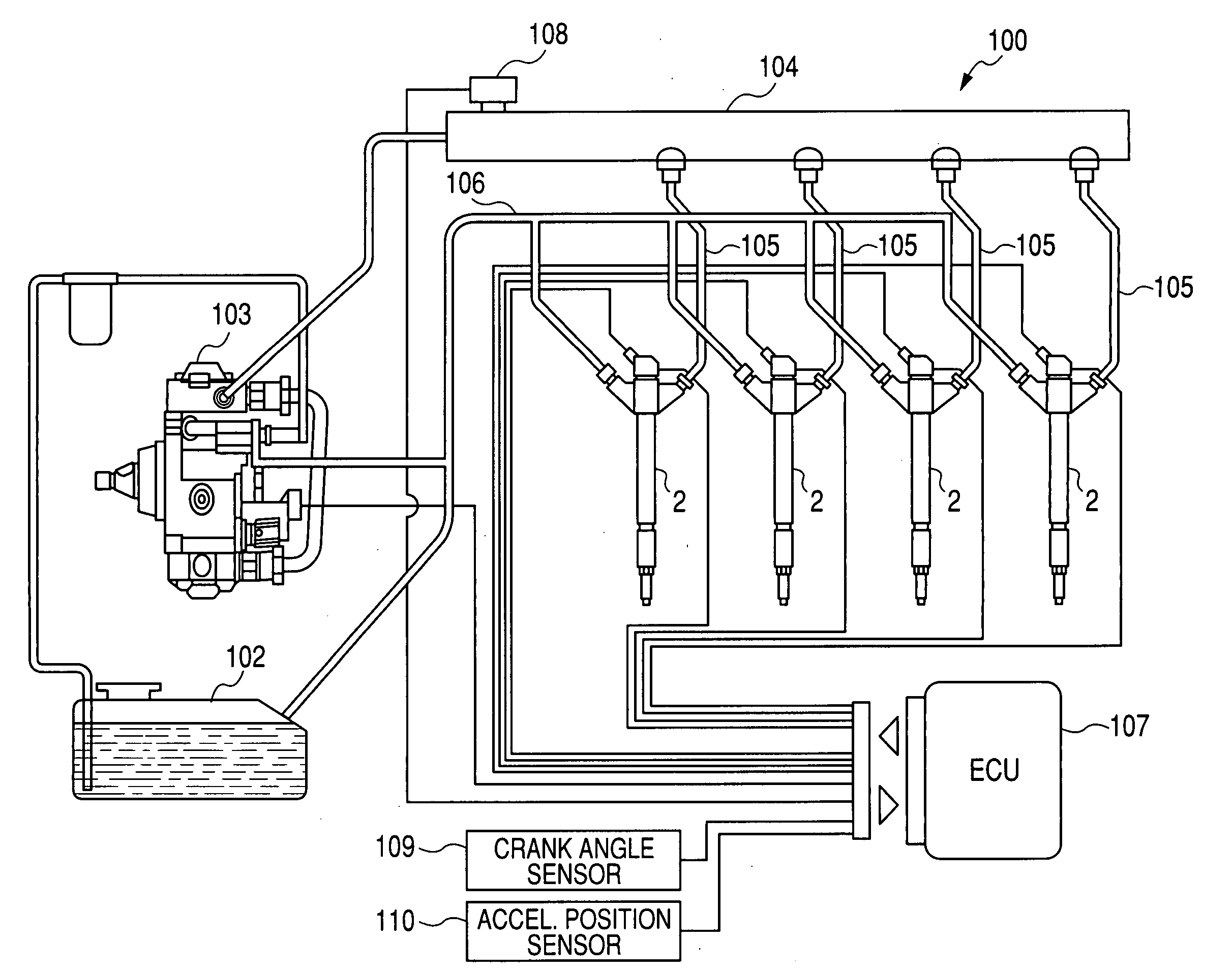
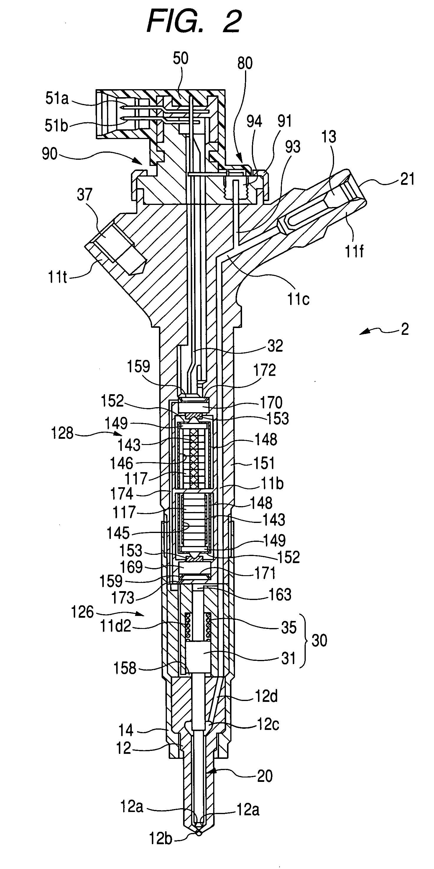
[0086]The fuel injectors 2 of the second embodiment will be described below with reference to FIGS. 7 and 8 which may be employed in the accumulator fuel injection system 100 of FIG. 1. The same reference numbers, as employed in the above embodiment, will refer to the same parts, and explanation thereof in detail will be omitted here.
first embodiment
[0087]The structure of the fuel injector 2 is different from that in the first embodiment in that the metal stem 94 is installed through the base of the head body 90 threadably in the upper end of the injector body.
[0088]Specifically, the injector body has a cylindrical hole 11i formed in the upper end thereof. The cylindrical hole 11i has a depth shorter than the length of the metal stem 94 and defines a portion of a sensor mount chamber in which the metal stem 94 is disposed. The hole 11i has an internal thread formed on an inner circumference thereof. The branch path 93 extends from the bottom of the hole 11i to the fuel inlet path 11c.
[0089]The head body 90 has a cylindrical hole 95a formed through the thickness of the base thereof. The hole 95a defines the sensor mount chamber together with the cylindrical hole 11i of the injector body. The installation of the metal stem 94 in the injector body is achieved by inserting the metal stern 94 into the hole 95a and screwing it into ...
third embodiment
[0092]The fuel injectors 2 of the third embodiment will be described below with reference to FIG. 9 which may be employed in the accumulator fuel injection system 100 of FIG. 1. The same reference numbers, as employed in the above embodiments, will refer to the same parts, and explanation thereof in detail will be omitted here.
[0093]The fuel injector 2 of the first embodiment is designed to have the head body 90 attached detachably to the upper end of the injector body (i.e., the actuator body 151) and the fuel pressure sensor 80 installed in the head body 90. Specifically, an assembly of the head body 90, the metal stem 94, and the pressure sensor chip 18f is prepared and then secured to the actuator body 151. In contrast, the fuel injector 2 of the third embodiment is designed not to have the head body 90, but to have a fuel pressure-sensing unit 940 made up of the metal stem 94 and the pressure sensor chip 18f.
[0094]The actuator body 151 has a cylindrical boss 151a formed on the...
PUM
 Abstract
Description
Claims
Application Information
 - R&D
- Intellectual Property
- Life Sciences
- Materials
- Tech Scout
- Unparalleled Data Quality
- Higher Quality Content
- 60% Fewer Hallucinations
Browse by: Latest US Patents, China's latest patents, Technical Efficacy Thesaurus, Application Domain, Technology Topic, Popular Technical Reports.
© 2025 PatSnap. All rights reserved.Legal|Privacy policy|Modern Slavery Act Transparency Statement|Sitemap|About US| Contact US: help@patsnap.com


