Reconstrainable stent delivery system

Active Publication Date: 2010-04-15
FLEXIBLE STENTING SOLUTIONS
View PDF100 Cites 145 Cited by
  • Summary
  • Abstract
  • Description
  • Claims
  • Application Information

AI Technical Summary

Benefits of technology

[0011]The present invention comprises a catheter delivery system for self-expanding stents. The reconstrainable stent delivery system of the present invention comprises a proximal end and distal end, which include inner and outer members, typically shafts or catheter or outer sheath of the catheter, which is crimped onto a slider at the proximal end of the stent. The slider can rotate about and move longitudinally along one of an inner shaft or tube, such as the guide wire tube, such that the proximal end of the stent can move distally as the stent deploys. A pusher can be used on the guide wire tube such that the guide wire tube, pusher, and stent move proximally relative to the outer sheath and reconstrain the stent in the outer sheath. Furthermore, the pusher and guide wire tube could move distally as the outer sheath retracts proximally for stent deployment to accommodate foreshortening.
[0012]The delivery system can also include a spring element in the catheter delivery system that will react the axial load at the proximal end of the stent during stent deployment. A spring element as described can bias the axial movement of the stent inside the delivery catheter to move distally as the stent is deployed. This biased movement is beneficial for stents that foreshorten an appreciable amount as the biased movement reduce the amount of movement at the distal end of the stent during stent deployment.
[0014]The stent of the present invention combines a helical strut member or band interconnected by coil elements. This structure provides a combination of attributes that are desirable in a stent, such as, for example, substantial flexibility, stability in supporting a vessel lumen, cell size and radial strength. However, the addition of the coil elements interconnecting the helical strut band complicates changing the diameter state of the stent. Typically, a stent structure must be able to change the size of the diameter of the stent. For instance, a stent is usually delivered to a target lesion site in an artery while in a small diameter size state, then expanded to a larger diameter size state while inside the artery at the target lesion site. The structure of the stent of the present invention provides a predetermined geometric relationship between the helical strut band and interconnected coil elements in order to maintain connectivity at any diameter size state of the stent.

Problems solved by technology

However, the addition of the coil elements interconnecting the helical strut band complicates changing the diameter state of the stent.

Method used


Image

  • Reconstrainable stent delivery system
  • Reconstrainable stent delivery system
  • Reconstrainable stent delivery system

Examples


Embodiment Construction

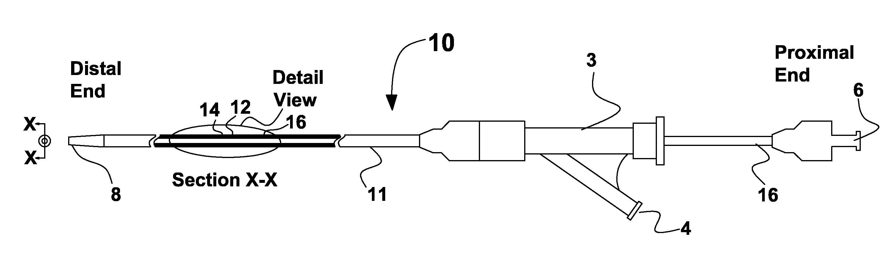
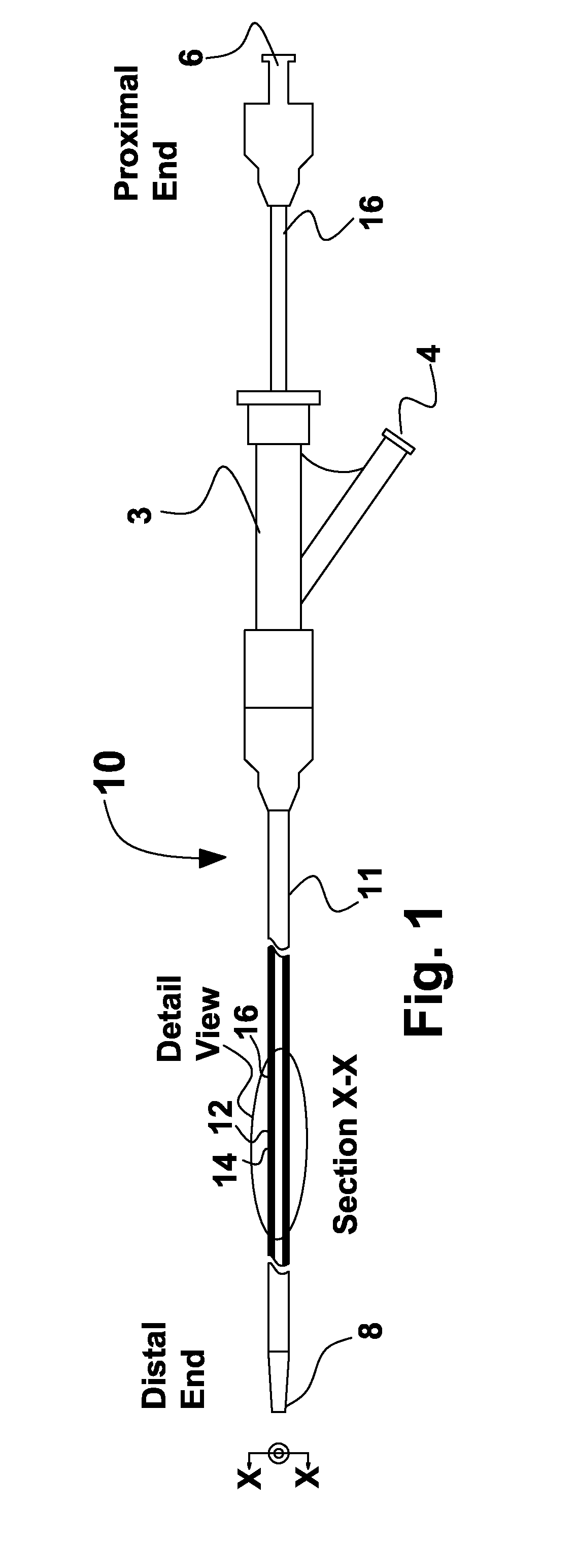
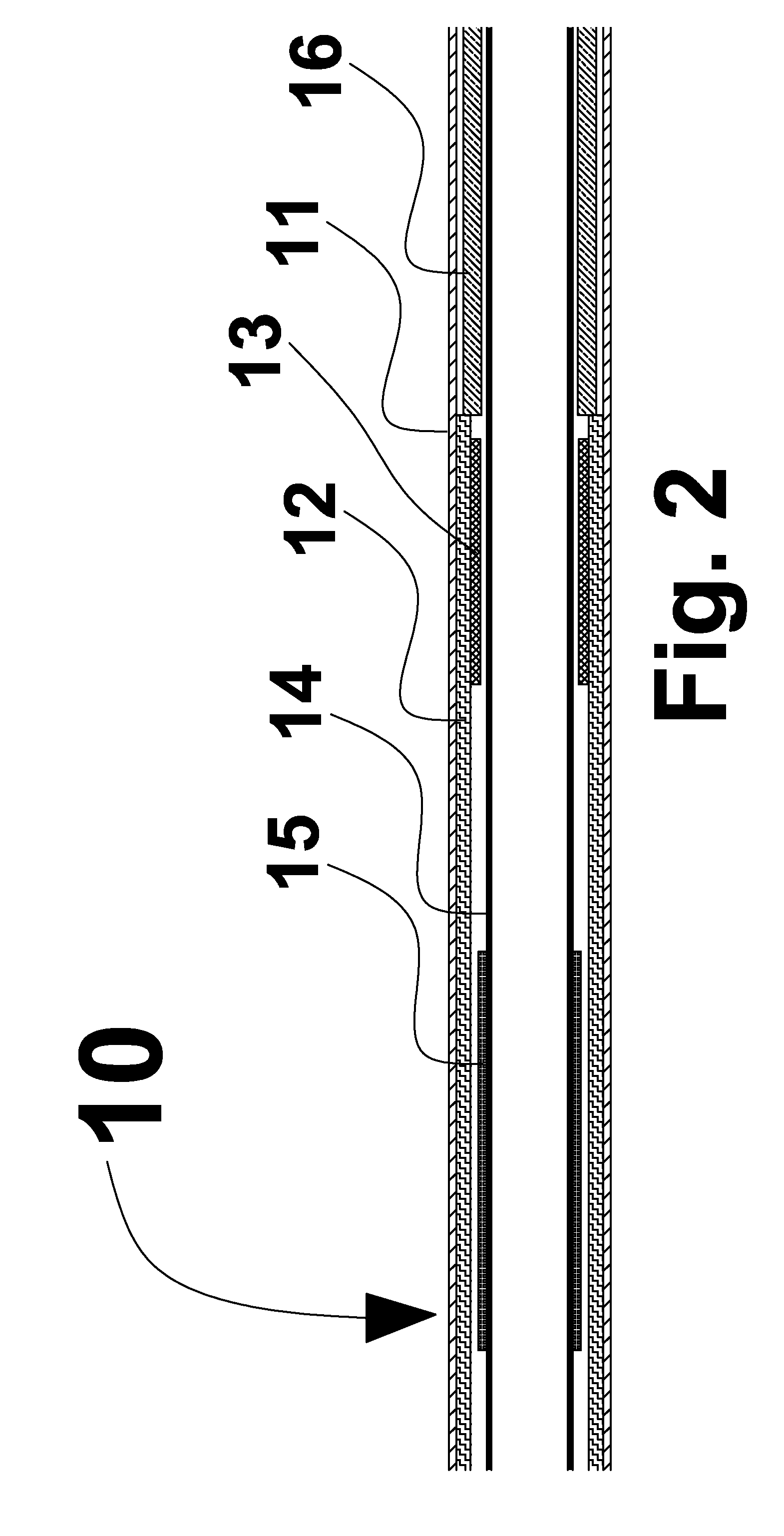
[0039]The self expanding stent delivery system 10 of the present invention is shown in FIG. 1 and is comprised of inner and outer coaxial members, for example a shaft or tube. The outer tube which is also known as outer sheath 11, constrains stent 12 in a crimped or radially compressed state. The inner members can be comprised of multiple components including distal tip 8, guide wire tube 14 and pusher 16 to react the axial forces placed on the stent as the outer sheath is retracted to deploy the stent. Pusher 16 can also act as a proximal stop. Other elements of the stent delivery system can include luer lock hub 6 attached to the proximal end of pusher 16, handle 3 attached to outer sheath 11 that incorporates luer port 4 such that the space between the inner members and outer sheath 11 can be flushed with saline solutions to remove any entrapped air. Pusher 16 is sometimes a composite structure of multiple components, such as a stainless steel tube at the proximal end and a polym...


PUM


Abstract

The stent of the present invention combines a helical strut band interconnected by coil elements. This structure provides a combination of attributes that are desirable in a stent, such as, for example, substantial flexibility, stability in supporting a vessel lumen, cell size and radial strength. The structure of the stent of the present invention provides a predetermined geometric relationship between the helical strut band and interconnected coil.

Description

CROSS REFERENCE TO RELATED APPLICATION[0001]This application claims the benefit of U.S. Provisional Patent Application No. 61 / 103,073, filed Oct. 6, 2008, the entirety of which is hereby incorporated by reference into this application.BACKGROUND OF THE INVENTION[0002]1. Field of the Invention[0003]This invention pertains to a self expanding stent and delivery system for a self expanding stent. The delivery system allows for reconstraining the stent into the delivery catheter simultaneously allowing the stent to change lengths and rotate inside the delivery catheter if required. This invention also pertains to a delivery system for self expanding stent that foreshortens an appreciable amount, for example more than about 10%.[0004]2. Description of the Related Art[0005]Most commercial self expanding stents are not designed to be recaptured (reconstrained) into the delivery system once the stent has started to expand into the target vessel, artery, duct or body lumen. It would be advan...

Claims


Application Information

Patent Timeline
IPC IPC(8): A61F2/84
CPCA61F2/88A61F2/91A61F2/915A61F2/962A61F2/966A61F2002/91558A61F2230/0054A61F2/95A61F2002/9534A61F2/86A61F2/958A61M25/01A61M25/09
Inventor BEACH, BRADLEYBURPEE, JANETFILACHEK, ANDREW
Owner FLEXIBLE STENTING SOLUTIONS
Why Eureka
Try Eureka