
Sample handling device

a technology for handling devices and samples, applied in the field of sample handling devices, can solve the problems of not being practical, not being practical, and taking a significant amount of time to be prepared and/or analysed

Inactive Publication Date: 2010-04-15
ENVIRONMENTAL BIOTECH CRC
View PDF0 Cites 32 Cited by
  • Summary
  • Abstract
  • Description
  • Claims
  • Application Information

AI Technical Summary

Benefits of technology

[0101]Typically the drive includes a stepper motor operatively coupled to the axle to thereby cause movement of the axle.

Problems solved by technology

First, this requires that the sample is transported to the centralised laboratory facility, in which case results can take a significant amount of time to be prepared and / or analysed. Often in cases where a disease or water-borne contamination is being tracked it is essential to have a rapid response and therefore this is not a practical solution.
Second, even when the time delay imposed by transfer of the sample is not a problem, there can be inherent problems in the process of collecting the sample and preparing this for transportation. For example, it is important to ensure that the sample cannot become contaminated, or cross contaminated as a result of the sampling process or subsequent sample handling process. Additionally, it may be necessary to treat a sample so that the sample remains viable or is stabilised until the analysis can be performed.
This may require that the individual collecting the sample is a skilled individual, which may not be a practical solution.
Whilst portable lab equipment has also been provided for allowing tests to be performed in situ, such equipment is generally expensive, complex and difficult to operate.
Additionally such equipment also often requires skilled operators at the location where the tests are performed, which as mentioned above is often not a viable solution.
However, again this requires the use of complex test apparatus, which is not suitable for use in all environments, and typically requires a trained operator.
However, this provides limited control over the process, and as a result the complexity of tests that can be performed is limited, thereby severely limiting the applications for which the device may be used.

Method used


Image

  • Sample handling device
  • Sample handling device
  • Sample handling device

Examples


Embodiment Construction

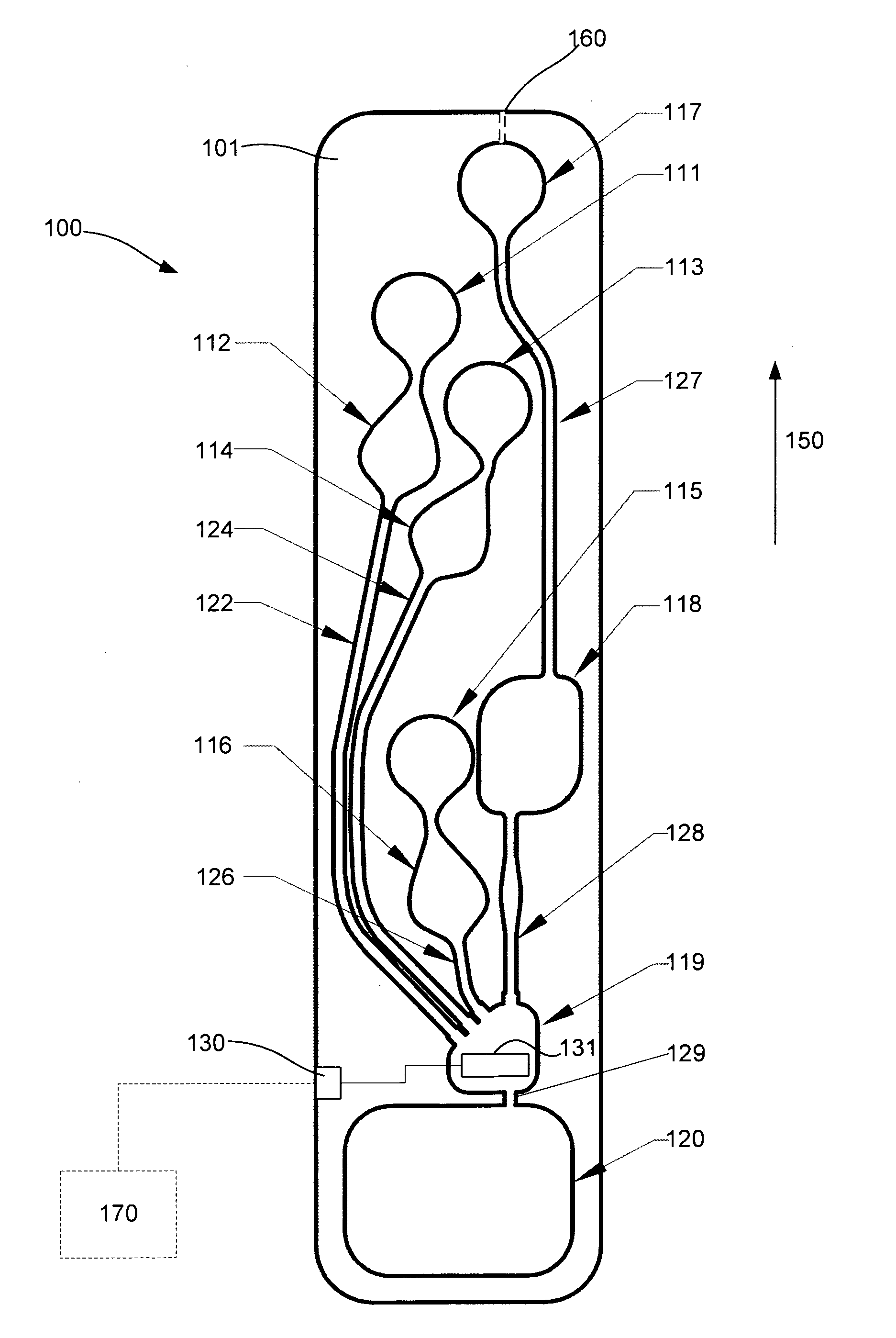
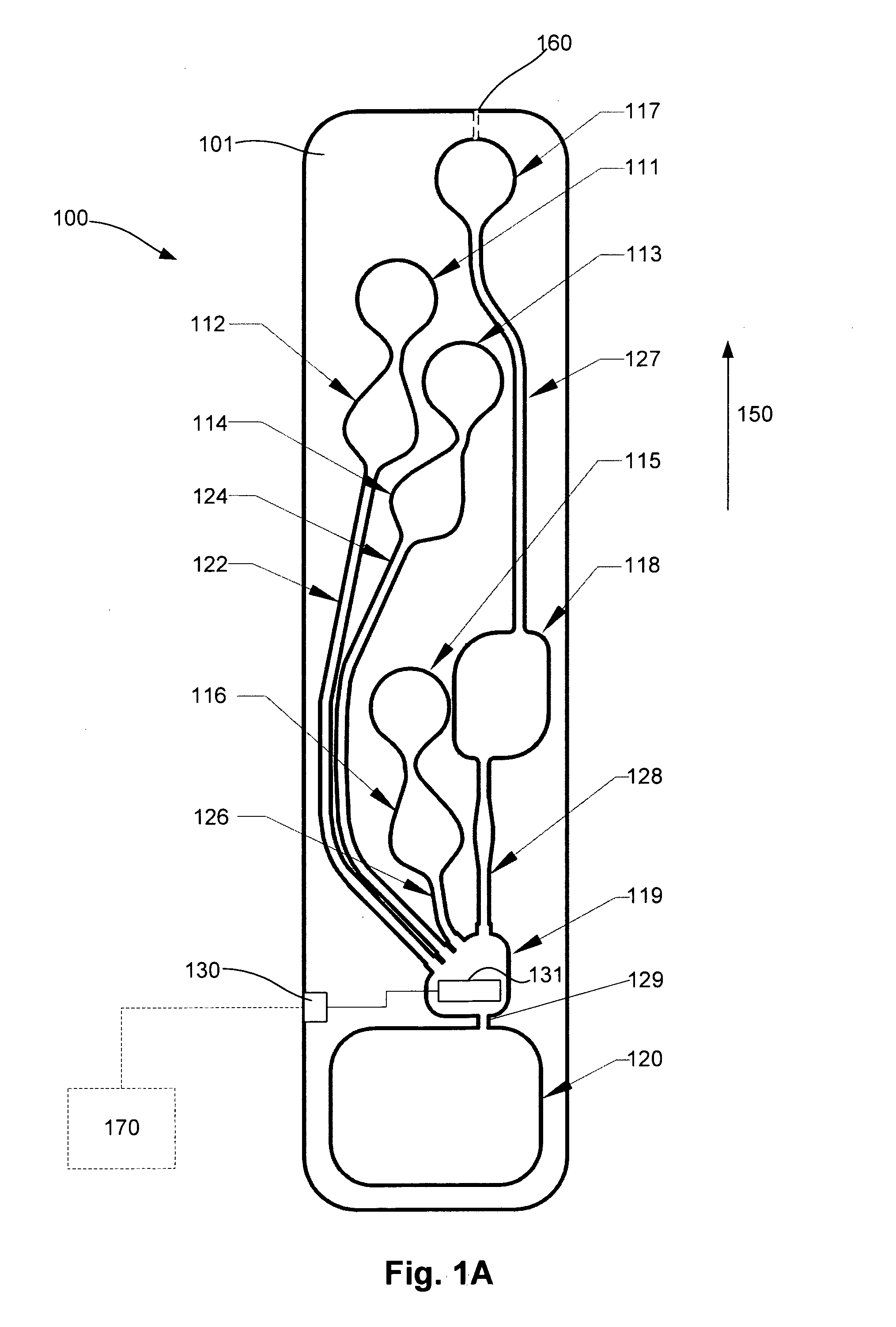
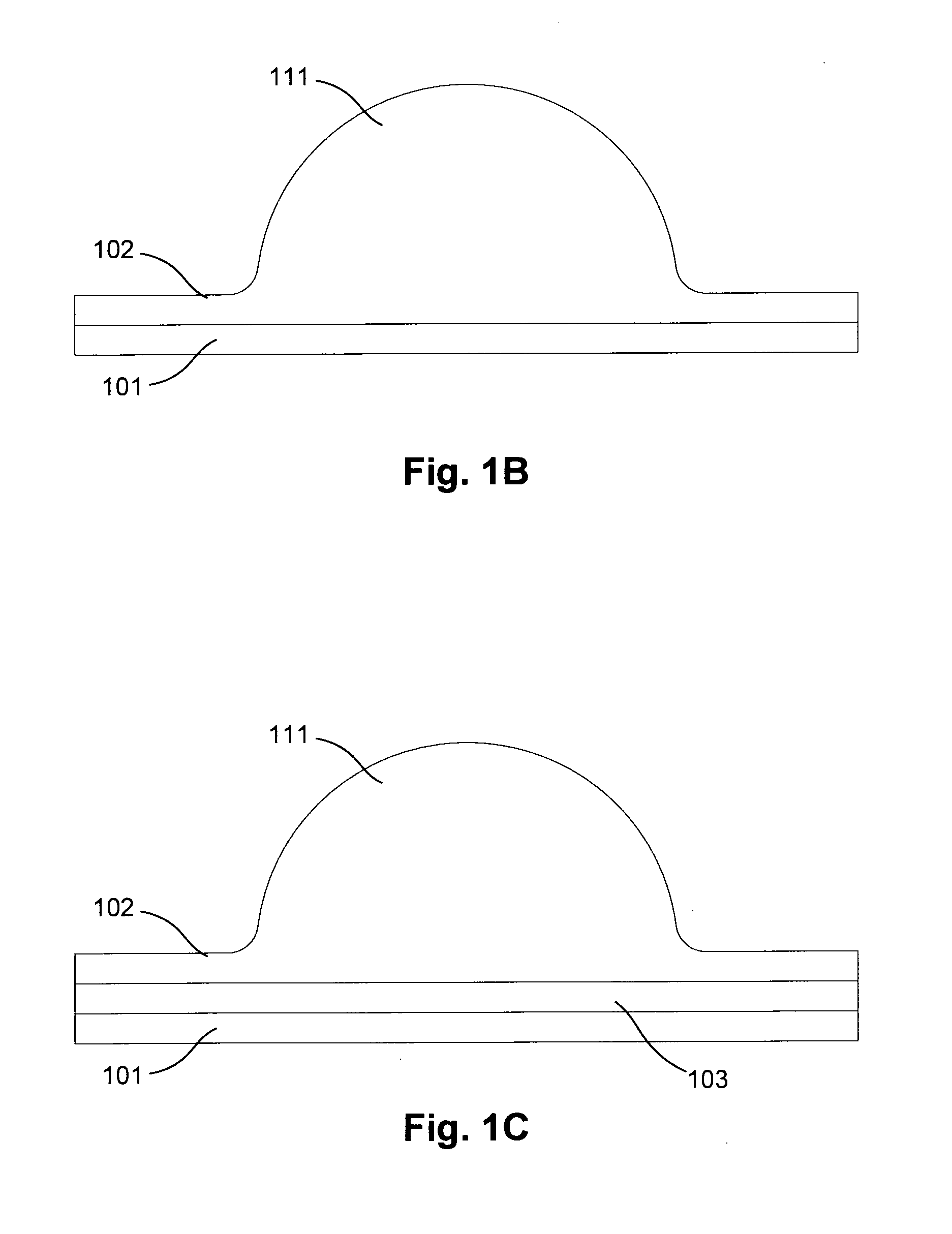
[0145]An example of a sample handling device for use in handling a sample to thereby allow the sample to be at least one of treated, stored, prepared for storage or used in an indicator test, will now be described with reference to FIGS. 1A and 1B.

[0146]In this example, the device 100 includes a substrate 101 having a number of cavities 111, 112, 113, 114, 115, 116, 117, 118, 119, 120 provided thereon, the cavities being connected via a number of fluid channels 122, 124, 126, 127, 128 and 129.

[0147]In one example, the cavities and / or the fluid channels are formed by a layer of material 102 provided on the substrate, which includes raised portions that define the fluid channels and cavities. A layer of material of this form will generally be referred to as a “cover layer”, and this is for the purpose of example only, and is not intended to be limiting.

[0148]Substances, such as reagents or the like, which are used in handling the sample, can be provided in selected ones of the cavitie...


PUM

PropertyMeasurementUnit
Timeaaaaaaaaaa
Pressureaaaaaaaaaa
Volumeaaaaaaaaaa

Abstract

A device for use in handling a sample, the device including a number of deformable cavities provided on a surface of a substrate, at least one of the cavities being a sample cavity for receiving a sample and a number of fluid channels connecting the cavities such that in use, selective deformation of the cavities causes the sample to be selectively combined with one or more substances.

Description

BACKGROUND OF THE INVENTION[0001]The present invention relates to a device and method for handling a sample, and in particular to a device and method for preparing a sample for use in an indicator test, and optionally for performing an indicator test.DESCRIPTION OF THE PRIOR ART[0002]The reference in this specification to any prior publication (or information derived from it), or to any matter which is known, is not, and should not be taken as an acknowledgment or admission or any form of suggestion that the prior publication (or information derived from it) or known matter forms part of the common general knowledge in the field of endeavour to which this specification relates.[0003]There is a growing need to be able to perform a wide variety of indicating tests in remote environments away from available laboratory facilities. This includes, for example, the ability to test for infection, diseases, environmental contamination, detecting pathogens in the environment, or the like. Cur...

Claims


Application Information

Patent Timeline
IPC IPC(8): C12Q1/04C12M1/00
CPCB01F3/12F16K2099/0084B01F15/0205B01F15/0212B01F15/0226B01L3/50273B01L3/502738B01L7/52B01L2200/142B01L2200/16B01L2300/069B01L2300/0816B01L2300/0864B01L2300/0867B01L2300/087B01L2400/0481B01L2400/0605B01L2400/0683F16K99/0001F16K99/0015F16K99/003F16K99/0059F16K2099/0078B01F13/0059B01F23/50B01F33/30B01F35/713B01F35/7137B01F35/7164
Inventor DITCHAM, WILLIAM GRAHAM FOXREID, SIMON ANDREW
Owner ENVIRONMENTAL BIOTECH CRC
Learn More