
Double Broken Seal Ring

a sealing ring and double-broken technology, applied in the direction of liquid/solution decomposition chemical coating, superimposed coating process, resistive material coating, etc., can solve the problem of unwanted noise/signal propagation, the use of seal rings, and the deformation of ic performance without sealing rings, so as to reduce noise propagation and minimize the amount of moisture penetrating the ic

Inactive Publication Date: 2010-04-08
QUALCOMM INC
View PDF34 Cites 23 Cited by
  • Summary
  • Abstract
  • Description
  • Claims
  • Application Information

AI Technical Summary

Benefits of technology

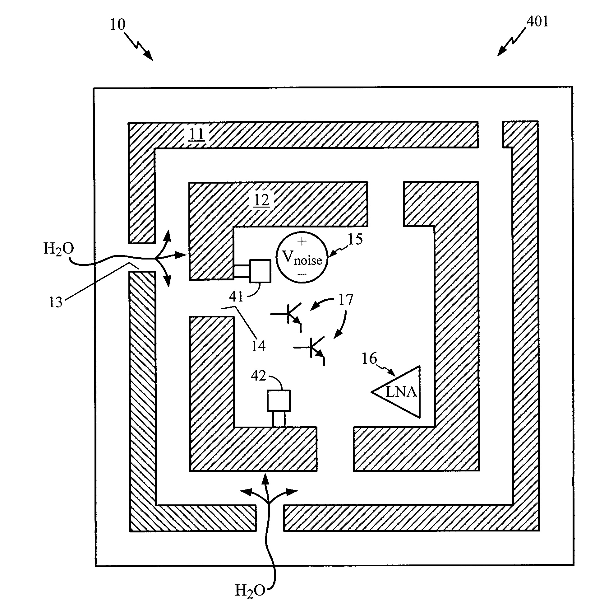
[0006]The present disclosure is directed to a method of fabricating a broken seal ring that will reduce noise propagation by breaking the seal ring conduction path while also minimizing the amount of moisture penetrating the IC.

Problems solved by technology

That is, over time, as the IC is exposed to moisture, the IC performance may degrade without the use of a seal ring.
However, use of these seal rings also has disadvantages, including unwanted noise / signal propagation.
Many times, a noise source, such as a digital signal input / output pad, clock input pad, power amplifier, etc., located on the IC causes noise to propagate along the seal ring, which subsequently can interfere with the operation of other devices on the IC.
This is problematic because the devices on the IC are not then isolated from each other as may otherwise be intended and designed.
This helps to reduce the noise propagation problem, but poses a risk to reliability because moisture can enter the IC through these breaks in the seal ring and degrade the device performance over time.

Method used


Image

  • Double Broken Seal Ring
  • Double Broken Seal Ring
  • Double Broken Seal Ring

Examples


Embodiment Construction

[0017]FIG. 1A is a schematic drawing of an IC 100, such as a radio frequency (RF) IC, with a conventional seal ring 51. The seal ring 51 has no breaks or interruptions. As discussed above, a signal produced by a noise source 15 may propagate along the seal ring 51 and interfere with the performance of other devices on the IC. For example, the IC 100 includes a low noise amplifier (LNA) 16, which is a device that is susceptible to the effects of noise. Because the LNA 16 is susceptible to noise, it has been located as far away on the IC 100 from the noise source 15 as possible. However, those having skill in the art would understand the LNA 16 will nevertheless be subject to the adverse effects of noise created by the noise source 15 due to propagation of noise through the seal ring 51.

[0018]FIG. 1B is a schematic drawing of an IC 101 with a different conventional seal ring 61. As discussed above, the seal ring 61 incorporates breaks, or openings, 62 in the seal ring 61. Such opening...


PUM

PropertyMeasurementUnit
widthaaaaaaaaaa
resistivityaaaaaaaaaa
structuresaaaaaaaaaa

Abstract

The amount of signal propagation and moisture penetration and corresponding reliability problems due to moisture penetration degradation in an IC can be reduced by fabricating two seal rings with non-adjacent gaps. In one embodiment, the same effect can be achieved by fabricating a wide seal ring with a channel having offset ingress and egress portions. Either of these embodiments can also have grounded seal ring segments which further reduce signal propagation.

Description

TECHNICAL FIELD[0001]The present disclosure generally relates to integrated circuits (ICs). More specifically, this disclosure relates to seal rings configurations to reduce signal propagation and to reduce moisture penetration.BACKGROUND[0002]Seal rings, which are rings composed of metals such as copper, aluminum, or gold, are fabricated around the perimeter of ICs to prevent IC cracking during the dicing process. An additional benefit in using a seal ring is that it serves as a barrier to moisture. That is, over time, as the IC is exposed to moisture, the IC performance may degrade without the use of a seal ring.[0003]However, use of these seal rings also has disadvantages, including unwanted noise / signal propagation. Many times, a noise source, such as a digital signal input / output pad, clock input pad, power amplifier, etc., located on the IC causes noise to propagate along the seal ring, which subsequently can interfere with the operation of other devices on the IC. This is pro...

Claims


Application Information

Patent Timeline
Patent Type & Authority Applications(United States)
IPC IPC(8): H01L23/02H05K3/28
CPCH01L23/562H01L23/564H01L23/585H01L2924/0002H01L2924/00H01L23/28H01L23/58
Inventor FREDERICK, JR., NORMANMYERS, TOM
Owner QUALCOMM INC
Learn More