
Method and system for adaptive coding in flash memories

a flash memory and adaptive coding technology, applied in the field of computer memory storage, can solve the problems of inability to erase a full block of cells, inability to program a mbc flash cell, and inability to store the desired “01” bit pattern in the second cell without erasing the cell

Inactive Publication Date: 2010-04-01
RAMOT AT TEL AVIV UNIV LTD
View PDF77 Cites 32 Cited by
  • Summary
  • Abstract
  • Description
  • Claims
  • Application Information

AI Technical Summary

Benefits of technology

[0036]Preferably, the first step attempts to set the value(s) of the physical parameter of the memory cell(s) so that the value(s) of the physical parameter that will ultimately represent all the bits is / are accessible from the value(s) that is / are set in the first step. By a physical parameter value being “accessible” is meant that the physical parameter can be adjusted to attain that value by programming the cell without having to erase the cell. For example, in FIG. 1B, a threshold voltage value in the (0,1) band is not accessible from the (0,0) threshold voltage band but a threshold voltage value in the (0,0) band is accessible from the (0,1) threshold voltage band.

Problems solved by technology

The programming of a MBC flash cell is not foolproof.
Physical effects, such as programming variations, program disturb and cross coupling, during the programming of the most significant bits and between the programming of the most significant bits and the programming of the least significant bits, might cause e.g. the second cell to be placed inadvertently in the >2V band before the least significant bits are programmed, thereby making it impossible for the second cell to store the desired “01” bit pattern without erasing the cell and starting over, because programming operations only increase the threshold voltage of a cell.
But flash memory cells are erased a full block of cells at a time and it is not practical to erase a full block of cells merely for correcting an error in a small number of cells.
After the wear and tear of many programming and erasure cycles, a flash cell may be stuck permanently in one of its threshold voltage states.

Method used


Image

  • Method and system for adaptive coding in flash memories
  • Method and system for adaptive coding in flash memories
  • Method and system for adaptive coding in flash memories

Examples


Embodiment Construction

[0056]The principles and operation of the programming of a memory such as a flash memory according to the present invention may be better understood with reference to the drawings and the accompanying description.

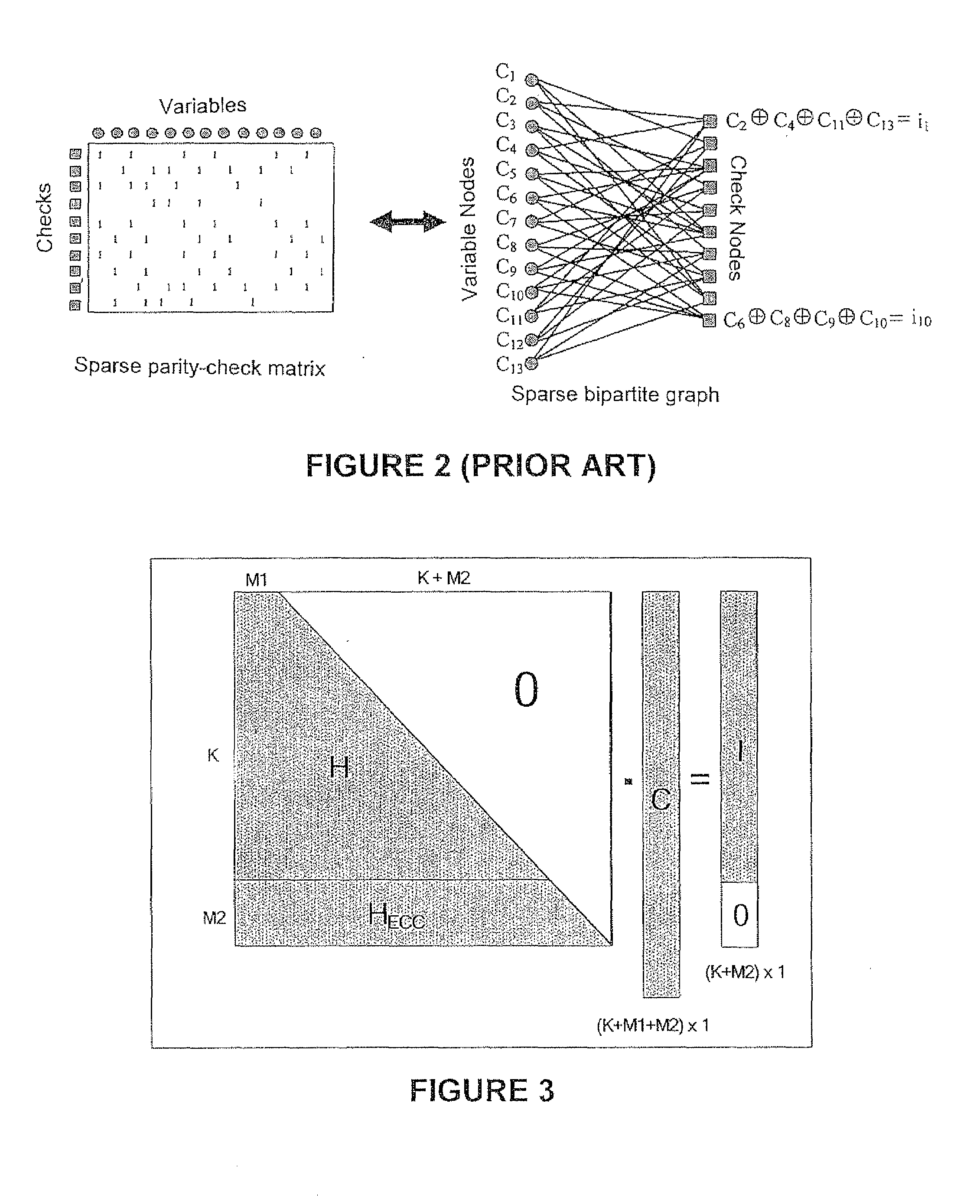
[0057]Two examples of code construction now will be described, with corresponding encoding and decoding algorithms. One code construction is suitable for “hard” feedback. The other code construction is suitable for “soft” feedback.

[0058]The described code constructions satisfy the following properties:[0059]Every vector of information bits is associated with multiple codewords.[0060]An efficient low-complexity encoding algorithm exists for the code. For a given set of “hard” / “soft” constraints on the desired codeword, the encoding algorithm allows low complexity encoding of the information vector into a codeword that satisfies all or most of the constraints as closely as possible with high probability.[0061]An efficient low-complexity decoding algorithm exists for the code,...


PUM


Abstract

Bits are stored by attempting to set parameter value(s) of (a) cell(s) to represent some of the bits. In accordance with the attempt, an adaptive mapping of the bits to value ranges is provided and the value(s) is / are adjusted accordingly as needed. Or, to store (a) bit(s) in (a) cell(s), a default mapping of the bit(s) to a predetermined set of value ranges is provided and an attempt is made to set the cell value(s) accordingly. If, for one of the cells, the attempt sets the value such that the desired range is inaccessible, an adaptive mapping is provided such that the desired range is accessible. Or, to store (a) bit(s) in (a) cell(s), several mappings of the bit(s) to a predetermined set of ranges is provided. Responsive to an attempt to set the cell value(s) according to one of the mappings, the mapping to actually use is selected.

Description

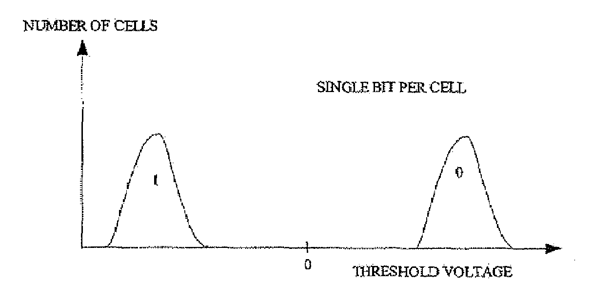
[0001]This patent application claims the benefit of U.S. Provisional Patent Application No. 61 / 100,732, filed Sep. 28, 2008FIELD AND BACKGROUND OF THE INVENTION[0002]The present invention relates to storing data in computer memories such as flash memories and, more particularly, to a method of storing data in a computer memory in a manner that enables the cells that store the data to include a small number of “bad” cells.[0003]Flash memory devices have been known for many years. Typically, each memory cell within a flash memory stores one bit of information. The traditional way to store a bit in a flash memory cell has been by supporting two states of the cell. One state represents a logical “0” and the other state represents a logical “1”. In a flash memory cell, the two states are implemented by having a floating gate above the cell's channel (the area connecting the source and drain elements of the cell's transistor), and having two valid states for the amount of charge stored wi...

Claims


Application Information

Patent Timeline
Patent Type & Authority Applications(United States)
IPC IPC(8): G06F12/00G06F12/02
CPCG11C29/00G11C2211/5641G11C11/5628G06F11/1072G11C7/1006G11C16/3404G06F12/00G11C16/06G11C16/34
Inventor LITSYN, SIMONSHARON, ERANALROD, IDANLASSER, MENAHEM
Owner RAMOT AT TEL AVIV UNIV LTD
Learn More