Magnetic head-positioning servo system, magnetic head test system and magnetic disk test system
a servo system and magnetic head technology, applied in the direction of magnetic recording, instruments, data recording, etc., can solve the problems of reducing the resonance frequency of the actuator, and reducing the positioning accuracy of the magnetic head, so as to achieve high positioning accuracy and increase the displacement
- Summary
- Abstract
- Description
- Claims
- Application Information
AI Technical Summary
Benefits of technology
Problems solved by technology
Method used
Image
Examples
first embodiment
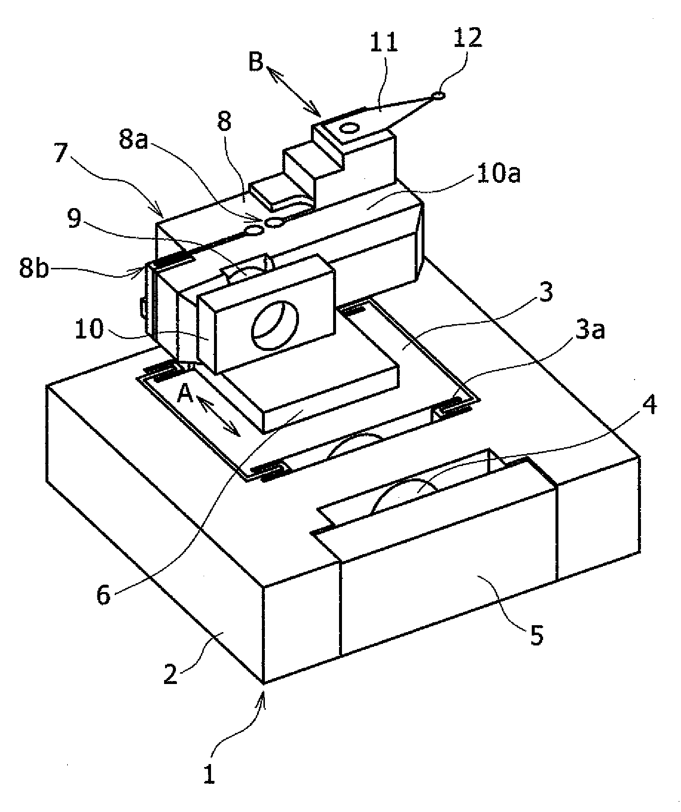
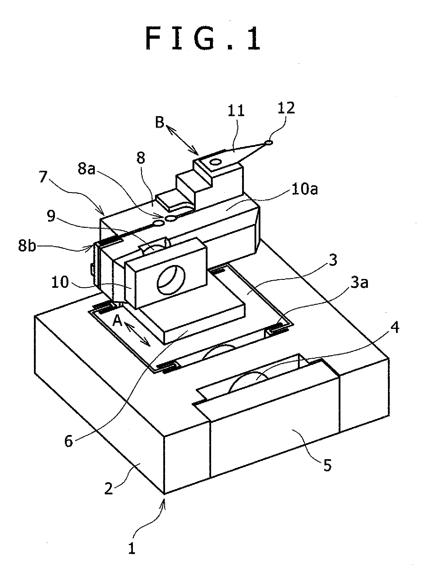
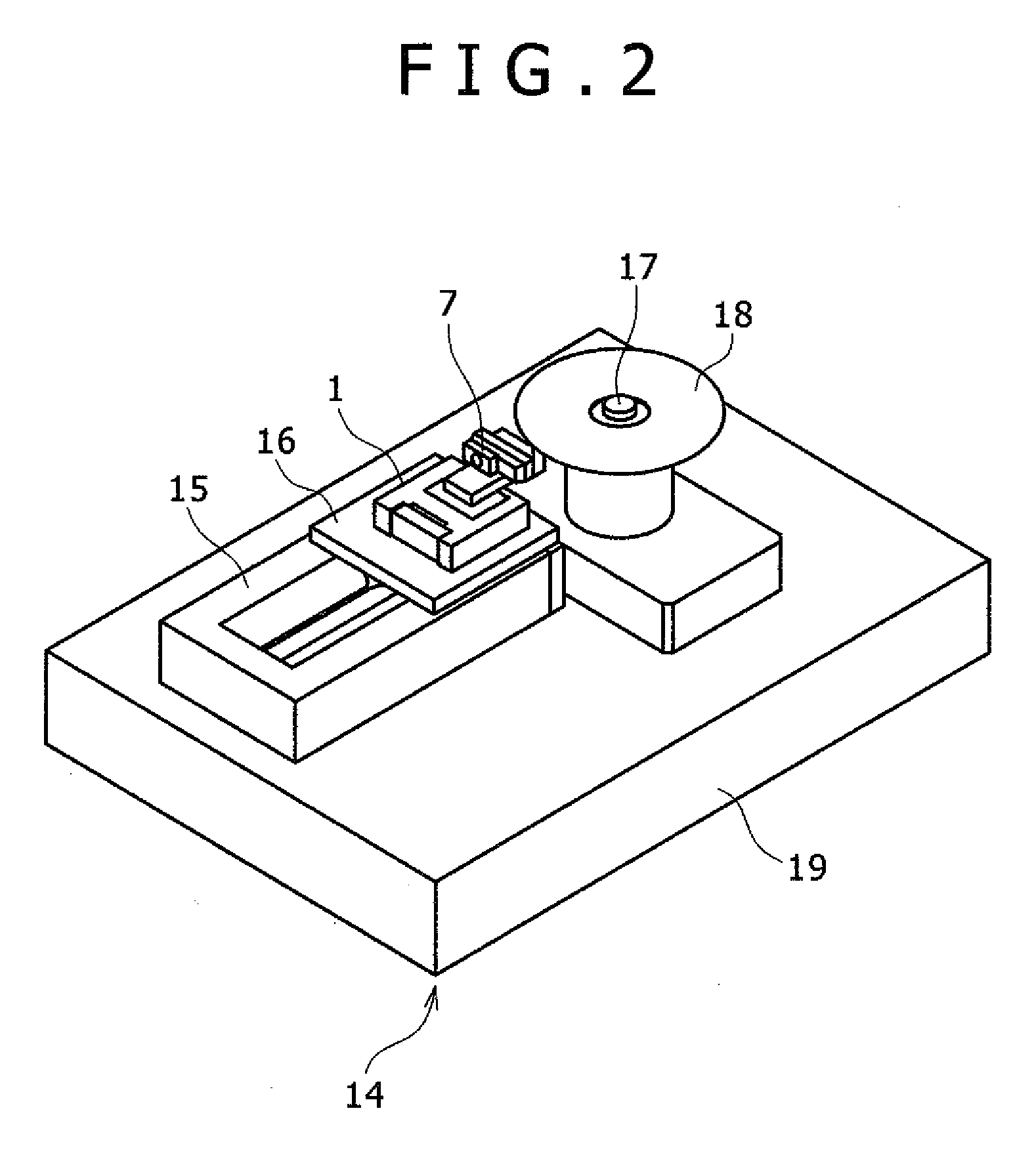
[0018]FIG. 1 is an overall view of the mechanical part of a magnetic head-positioning servo system according to a first embodiment. FIG. 2 is an overall view of the mechanical part of a magnetic disk test system using the magnetic head-positioning servo system shown in FIG. 1. FIG. 3 is a view showing the relation between a track and a magnetic disk to be tested by the magnetic disk test system shown in FIG. 2.
[0019]The magnetic disk test system is a system for testing the characteristics of a magnetic disk by a magnetic head reading the magnetic information written in advance to the magnetic disk as well as the magnetic information written to the magnetic disk by the magnetic head.
[0020]In FIG. 1, the mechanical part of the magnetic head-positioning servo system is configured such that a second fine actuator, namely a piezo-actuator 7 is mounted on a first fine actuator, namely a piezo-stage 1. The piezo-stage 1 includes a base 2, a moving table 3, support members 3a for supporting...
second embodiment
[0050]FIG. 5 is a schematic view of a magnetic head-positioning servo system according to a second embodiment. The mechanical part of the second embodiment is the same as that of the first embodiment.
[0051]The eccentricity compensation table data storage circuit 26 inputs an instruction value based on the eccentricity compensation table data that is prepared in advance to the piezo-actuator driver 27 to compensate the eccentricity.
[0052]The piezo-actuator driver 27 applies a voltage corresponding to the instruction value to the piezo-actuator 7 to compensate the eccentricity by the piezo-actuator 7.
[0053]The displacement of the piezo-stage 1 from the reference position is detected by the position sensor 30, and is input to the piezo-stage compensation circuit 29. The piezo-stage compensation circuit 29 inputs an instruction value to the piezo-stage driver 31.
[0054]Based on the instruction value from the piezo-stage compensation circuit 29, the piezo-stage driver 31 generates a drive...
third embodiment
[0058]FIG. 6 is a schematic view of a magnetic head-positioning servo system according to a third embodiment. The configuration of the mechanical part of the third embodiment is the same as those of the first and second embodiments.
[0059]The eccentricity compensation table data storage circuit 26 inputs an instruction value, based on the eccentricity compensation table data that is prepared in advance, to a current pulse-controlled piezo-actuator driver 32 to compensate the eccentricity.
[0060]The current pulse-controlled piezo-actuator driver 32 applies a current pulse corresponding to the instruction value to the piezo-actuator 7 to compensate the eccentricity by the piezo-actuator 7.
[0061]The displacement of the piezo-stage 1 from the reference position is detected by the position sensor 30, and is input to the piezo-stage compensation circuit 29.
[0062]The piezo-stage compensation circuit 29 inputs an instruction value to the piezo-stage driver 31.
[0063]Based on the instruction va...
PUM
 Abstract
Description
Claims
Application Information
 - R&D
- Intellectual Property
- Life Sciences
- Materials
- Tech Scout
- Unparalleled Data Quality
- Higher Quality Content
- 60% Fewer Hallucinations
Browse by: Latest US Patents, China's latest patents, Technical Efficacy Thesaurus, Application Domain, Technology Topic, Popular Technical Reports.
© 2025 PatSnap. All rights reserved.Legal|Privacy policy|Modern Slavery Act Transparency Statement|Sitemap|About US| Contact US: help@patsnap.com


