
Method for transmitting and identifying transmit power value in multi-user MIMO

a multi-user, transmitting power technology, applied in the field of multi-user mimo transmitting and identifying transmit power value, can solve problems such as large overhead, and achieve the effect of reducing the overhead of reception power and efficient quantizing transmit power ratio values

Active Publication Date: 2010-03-25
LG ELECTRONICS INC
View PDF12 Cites 13 Cited by
  • Summary
  • Abstract
  • Description
  • Claims
  • Application Information

AI Technical Summary

Benefits of technology

[0027]An object of the present invention is to provide a method for transmitting a transmit power ratio values in a minimum number of bits by efficiently quantizing a transmit power ratio values.
[0028]Another object of the present invention is to provide a method for reducing the overhead of reception power by identifying a transmit power ratio values using an efficiently quantized transmit power ratio values.
[0030]The objectives and other advantages of the invention may be realized and attained by the structure particularly pointed out in the written description and claims hereof as well as the appended drawings. To achieve these objects and other advantages and in accordance with the purpose of the invention, as embodied and broadly described herein, a method for transmitting, at a base station (BS), a transmit power ratio values of a spatially multiplexed signal to a UE in a BS in a multi-user MIMO scheme comprises calculating available transmit power ratios for respective layers, reducing a number of bits used to represent entire transmit power ratio values by allocating same bit value to a plurality of same transmit power ratio values among the calculated transmit power ratio values for the respective layers, quantizing a transmit power ratio values of symbols to be transmitted to the UE using the entire transmit power ratio values of the reduced number of bits, and transmitting the quantized transmit power ratio values to the UE.

Problems solved by technology

Conventionally, when a BS transmits a transmit power ratio value to a UE, a large overhead results.

Method used


Image

  • Method for transmitting and identifying transmit power value in multi-user MIMO
  • Method for transmitting and identifying transmit power value in multi-user MIMO
  • Method for transmitting and identifying transmit power value in multi-user MIMO

Examples


Embodiment Construction

[0043]Reference will now be made in detail to the preferred embodiments of the present invention with reference to the accompanying drawings. Those skilled in the art will appreciate that various modifications, additions, and substitutions to exemplary embodiments of the present invention, of which a detailed description will be given below, and the present invention is not limited to the exemplary embodiments.

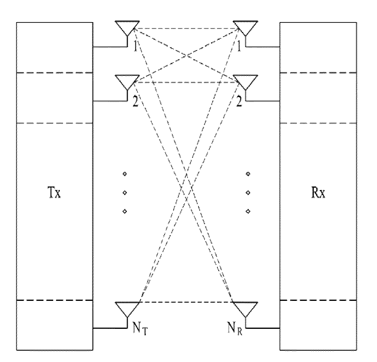
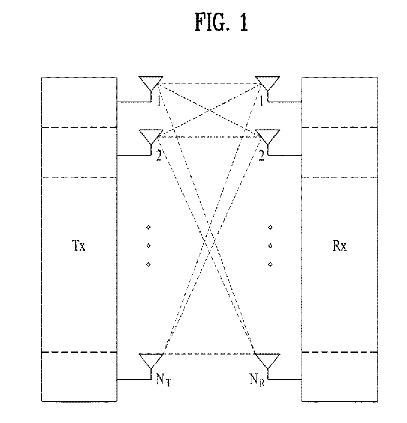
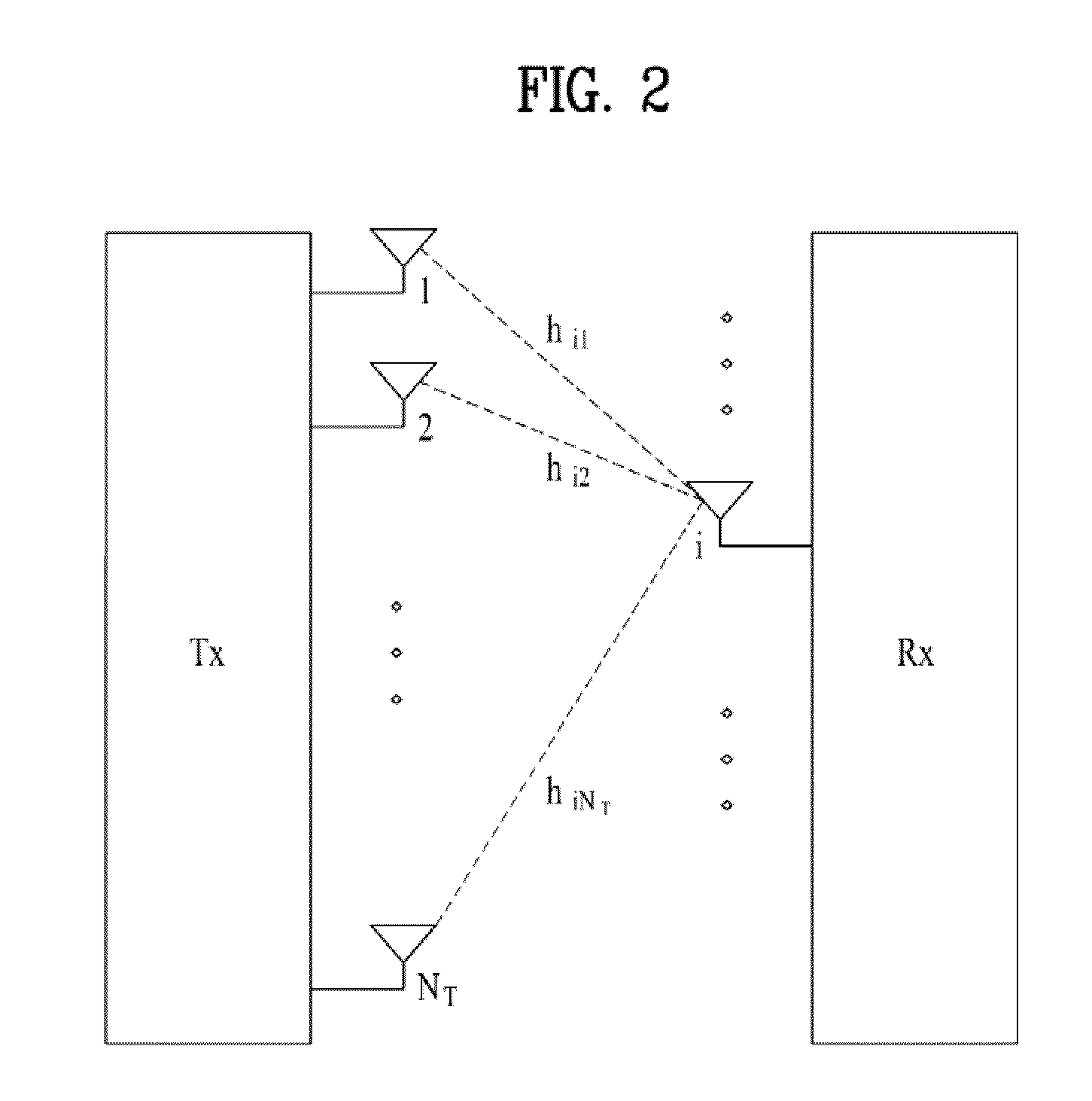
[0044]When a Base Station (BS) transmits spatially multiplexed signals to a plurality of User Equipments (UEs) on a downlink in a multi-user MIMO scheme, each UE need to get knowledge of the reception power of received information symbols for efficiently demodulate received information symbols. To this end, the UE may directly estimate the reception power of the reception signal, for example. Yet, to simplify the reception operation of the UE and prevent errors during reception power estimation, the BS may notify each UE of the transmit power of a signal transmitted to the spa...


PUM


Abstract

A method for transmitting and identifying a transmit power value in a multi-user MIMO scheme is disclosed. The transmit power value transmission method includes calculating available transmit power ratios for respective layers, reducing a number of bits used to represent entire transmit power ratio values by allocating same bit value to a plurality of same transmit power ratio values among the calculated transmit power ratio values for the respective layers; quantizing a transmit power ratio values of symbols to be transmitted to the UE using the entire transmit power ratio values of the reduced number of bits; and transmitting the quantized transmit power ratio values to the UE.

Description

CROSS-REFERENCE TO RELATED APPLICATIONS[0001]This application claims the benefit of Korean Patent Application No. 10-2008-0091709, filed on Sep. 18, 2008, which is hereby incorporated by reference as if fully set forth herein.BACKGROUND OF THE INVENTION[0002]1. Field of the Invention[0003]The present invention relates to a method for efficiently setting transmit power for each user in a system supporting spatial multiplexing using multiple Transmission (Tx) and Reception (Rx) antennas for data transmission between a Base Station (BS) and multiple users.[0004]2. Discussion of the Related Art[0005]Beyond the conventional use of a single Tx antenna and a single Rx antenna, Multi-Input Multi-Output (MIMO) is a technology for increasing the transmission and reception efficiency of data by use of a plurality of Tx antennas and a plurality of Rx antennas. That is, MIMO is a technology for increasing capacity and improving performance by use of multiple antennas at both a transmitter and a ...

Claims


Application Information

Patent Timeline
Patent Type & Authority Applications(United States)
IPC IPC(8): H04B7/00H04W4/00
CPCH04B7/0413Y02B60/50H04W52/42H04B7/0697Y02D30/70
Inventor AHN, JOON KUIROH, DONG WOOKKIM, BONG HOEKIM, KI JUN
Owner LG ELECTRONICS INC
Learn More