Eureka AIR delivers breakthrough ideas for toughest innovation challenges, trusted by R&D personnel around the world.

Refrigeration systems and methods for connection with a vehicle's liquid cooling system

a liquid cooling system and refrigeration system technology, applied in the field of refrigerators, can solve the problems of vapor cycle systems that refrigerators are prone to malfunction, and vapor cycle systems add significant weigh

Active Publication Date: 2010-03-25
BE AEROSPACE INCORPORATED
View PDF174 Cites 120 Cited by
  • Summary
  • Abstract
  • Description
  • Claims
  • Application Information

AI Technical Summary

Benefits of technology

[0008]A method of cooling a refrigerated compartment using a liquid cooling system of a vehicle may include using reducing a temperature of a refrigerated compartment to a desired temperature using a first chilled liquid coolant system coupled with a liquid cooling system of a vehicle and a second chilled coolant system together as a cascade cooling system. The method may also include maintain the temperature of the refrigerated compartment at approximately the desired temperature using the first chilled liquid coolant system coupled with the liquid cooling system of the vehicle without using the second chilled coolant system to when the desired temperature is equal to or greater than approximately 3 degrees C. The method may additionally include maintaining the temperature of the refr...

Problems solved by technology

Although conventional vapor cycle aircraft galley refrigerators are suitable for their intended purpose, they have several drawbacks.
One drawback is that the vapor cycle system of conventional refrigerators consume a significant amount of electrical energy.
In addition, the vapor cycle system adds numerous mechanical and electrical parts to a conventional refrigerator, thereby making the refrigerator prone to malfunction.
Furthermore, vapor cycle systems add significant weight and cause conventional refrigerators to occupy considerable space.

Method used


Image

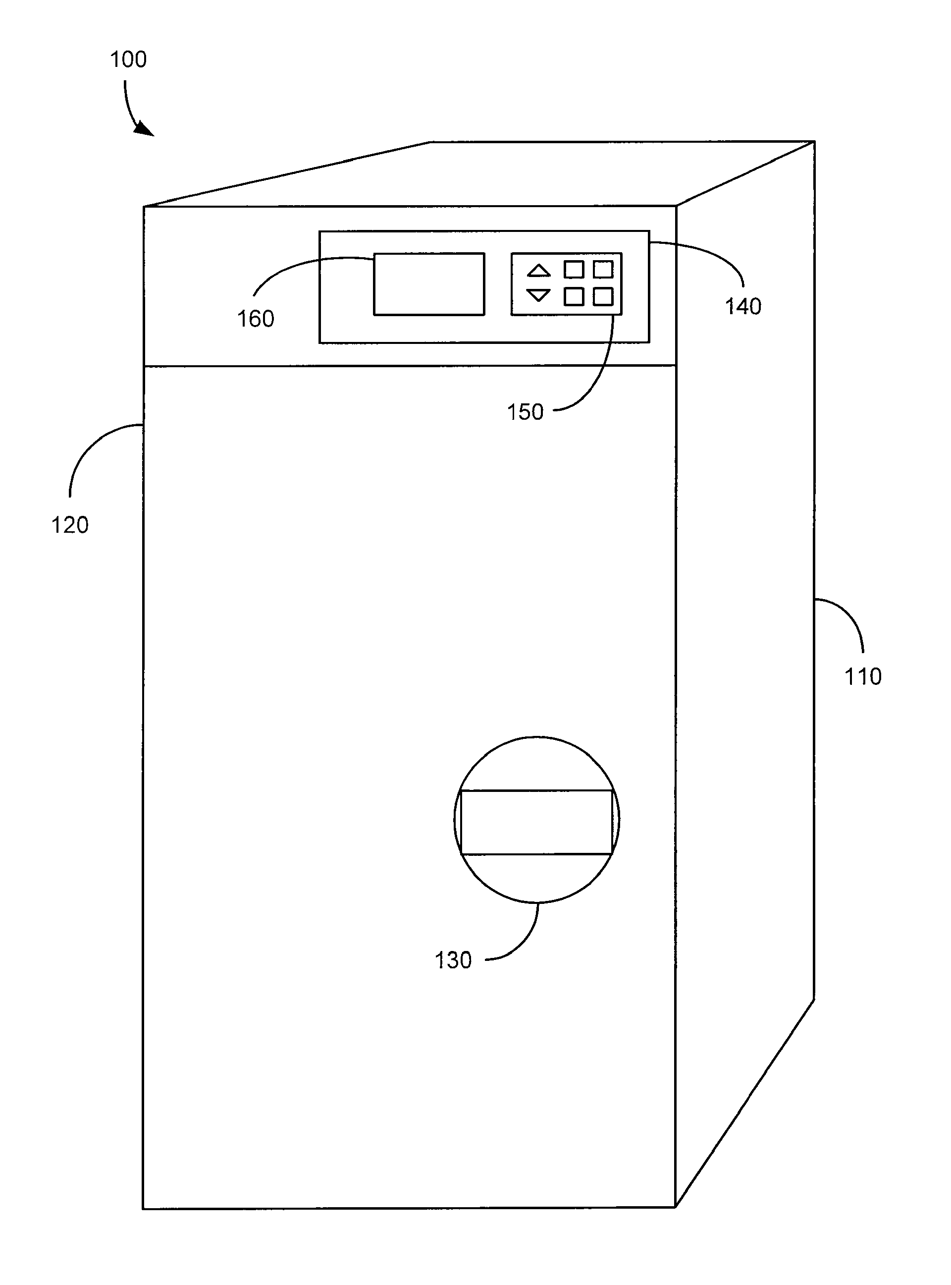
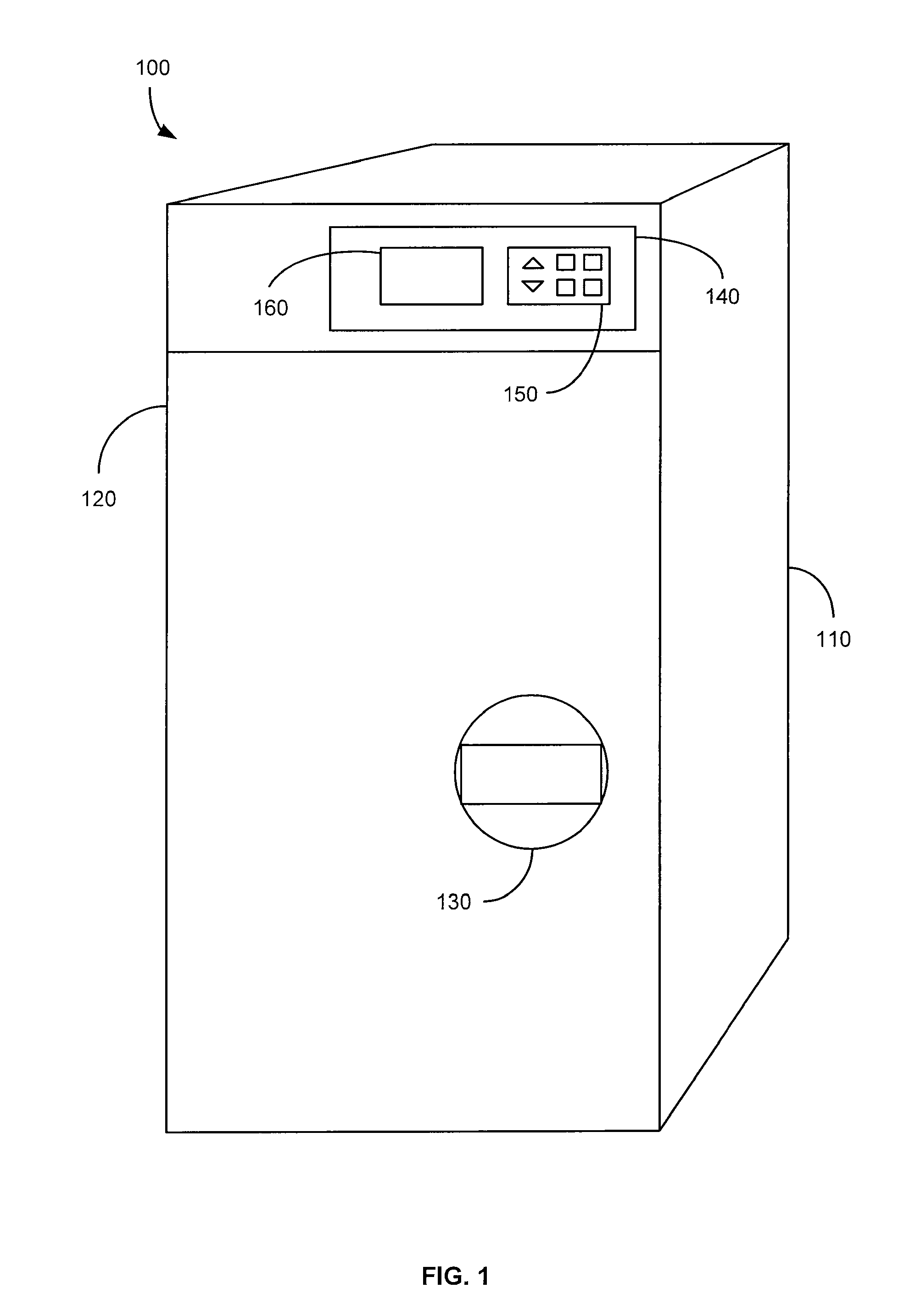
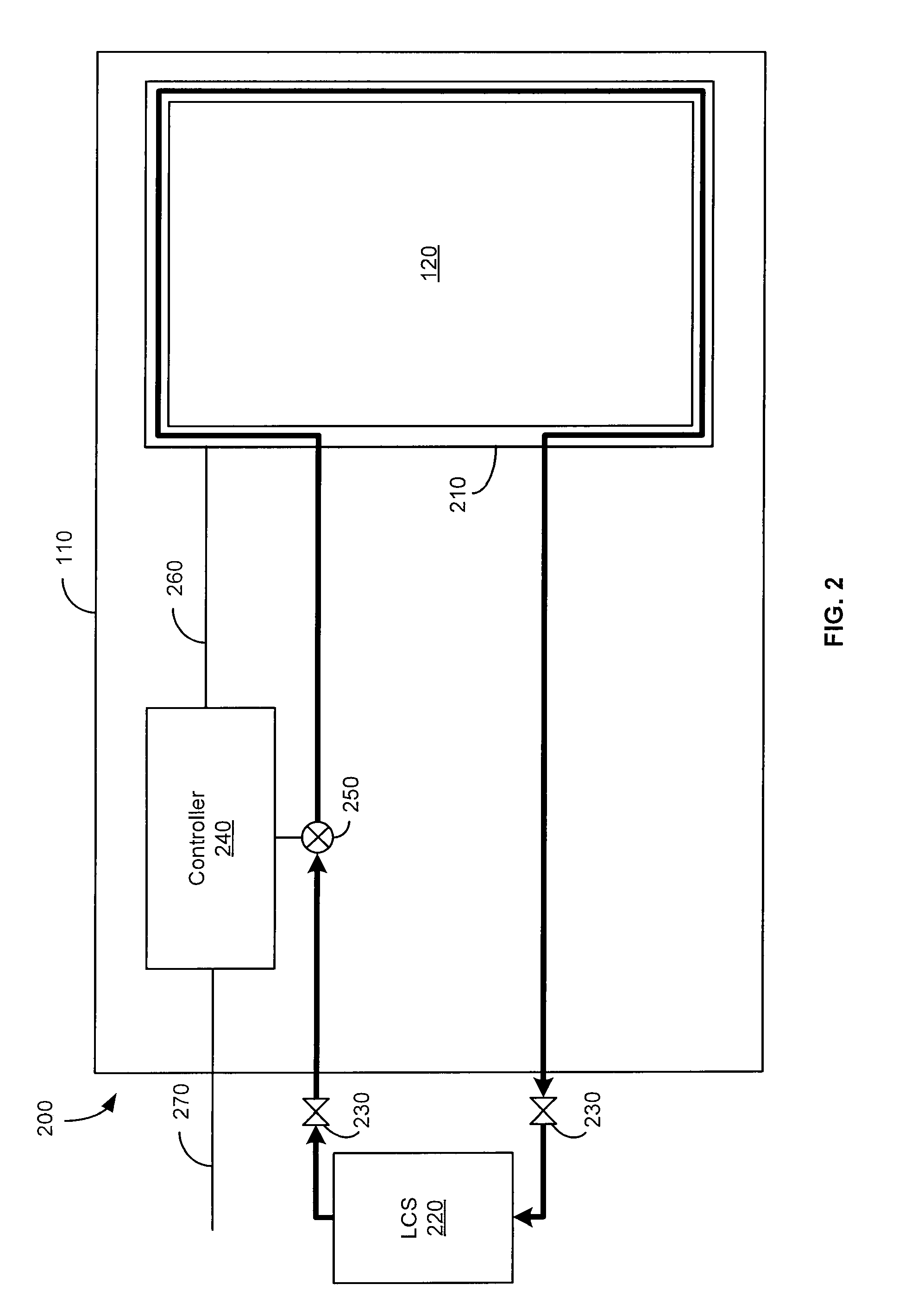
  • Refrigeration systems and methods for connection with a vehicle's liquid cooling system
  • Refrigeration systems and methods for connection with a vehicle's liquid cooling system
  • Refrigeration systems and methods for connection with a vehicle's liquid cooling system

Examples


Embodiment Construction

[0018]Vehicles, such as aircraft, have recently included a liquid cooling system (hereinafter referred to as an LCS). The LCS typically provides a centralized refrigeration system in which chilled coolant is distributed from a central location throughout the aircraft for use in providing cooling to plenums within galleys into which food trolleys / carts are configured, as well as in providing cooling to in-flight entertainment electronics. The LCS typically includes a central refrigeration unit, a pump, and a liquid coolant tubing loop for circulating a chilled liquid coolant (e.g., PGW, a solution of 60% propylene glycol and water by volume, or Galden coolant, etc.) The chilled liquid coolant may be maintained at a chilled temperature by the LCS, such as −8 degrees C. The chilled liquid coolant is typically pumped throughout the aircraft to all galleys and their respective food service trolleys after being chilled by the central refrigeration unit.

[0019]A galley refrigerator that con...


PUM


Abstract

An exemplary refrigeration system for cooling food or beverages may use a liquid cooling system of a vehicle. The refrigeration system may include a compartment in which the food or beverages may be placed and removed, a chilled liquid coolant system having a connection through which liquid coolant is received from the liquid cooling system of the vehicle, and a heat exchanger operationally coupled with the chilled liquid coolant system and the compartment to transfer heat from the compartment into the liquid coolant. The refrigeration system may also include a second chilled coolant system through which a second coolant flows and a second heat exchanger operationally coupled with the second chilled coolant system and the compartment to transfer heat from the compartment. The chilled liquid coolant system and the second chilled coolant system may operate together as a cascade cooling system.

Description

CROSS-REFERENCE TO RELATED PATENT APPLICATIONS[0001]This application claims the priority benefit under 35 U.S.C. §119(e) from U.S. Provisional Patent Application No. 61 / 100,170 entitled “Galley Refrigerator Connected to Aircraft Supplemental Cooling System” and filed Sep. 25, 2008, the entire content of which is incorporated herein by reference. This application also claims the priority benefit under 35 U.S.C. §119(e) from U.S. Provisional Patent Application No. 61 / 236,963 entitled “A Cascade Thermoelectric Device Cooling System Design for a Vehicle Three-Mode Refrigerator” and filed Aug. 26, 2009, the entire content of which is incorporated herein by reference.BACKGROUND[0002]1. Field of the Invention[0003]The present invention generally relates to refrigerators for use in a galley of a vehicle (e.g., an aircraft) for refrigerating food and beverage products. More specifically, the present invention relates refrigeration systems and methods for connection with a vehicle's liquid co...

Claims


Application Information

Patent Timeline
IPC IPC(8): F25B21/02F25B41/00F25D17/06G05D23/00F25B7/00
CPCB60H1/00592B64D11/04B64D2013/0629F25B7/00F25B21/02F25B2321/025F25D15/00F25D17/06F25D2700/12F25B2321/0212F25B2321/0252
Inventor LU, QIAOGODECKER, WILLIAM
Owner BE AEROSPACE INCORPORATED
Why Eureka
Eureka Blog
Learn More