
Blade pitch control

a technology of electric blades and blades, which is applied in the direction of rotors, marine propulsion, vessel construction, etc., can solve the problems of redundancy in methods, and achieve the effect of rapid control of blade pitch and large or small differences

Active Publication Date: 2010-03-18
ROLLS ROYCE PLC
View PDF60 Cites 12 Cited by
  • Summary
  • Abstract
  • Description
  • Claims
  • Application Information

AI Technical Summary

Benefits of technology

[0012]b. in the primary electrical control system, where there is a difference, applying a torque to a blade pitch regulator to reduce the magnitude of the difference to zero, and
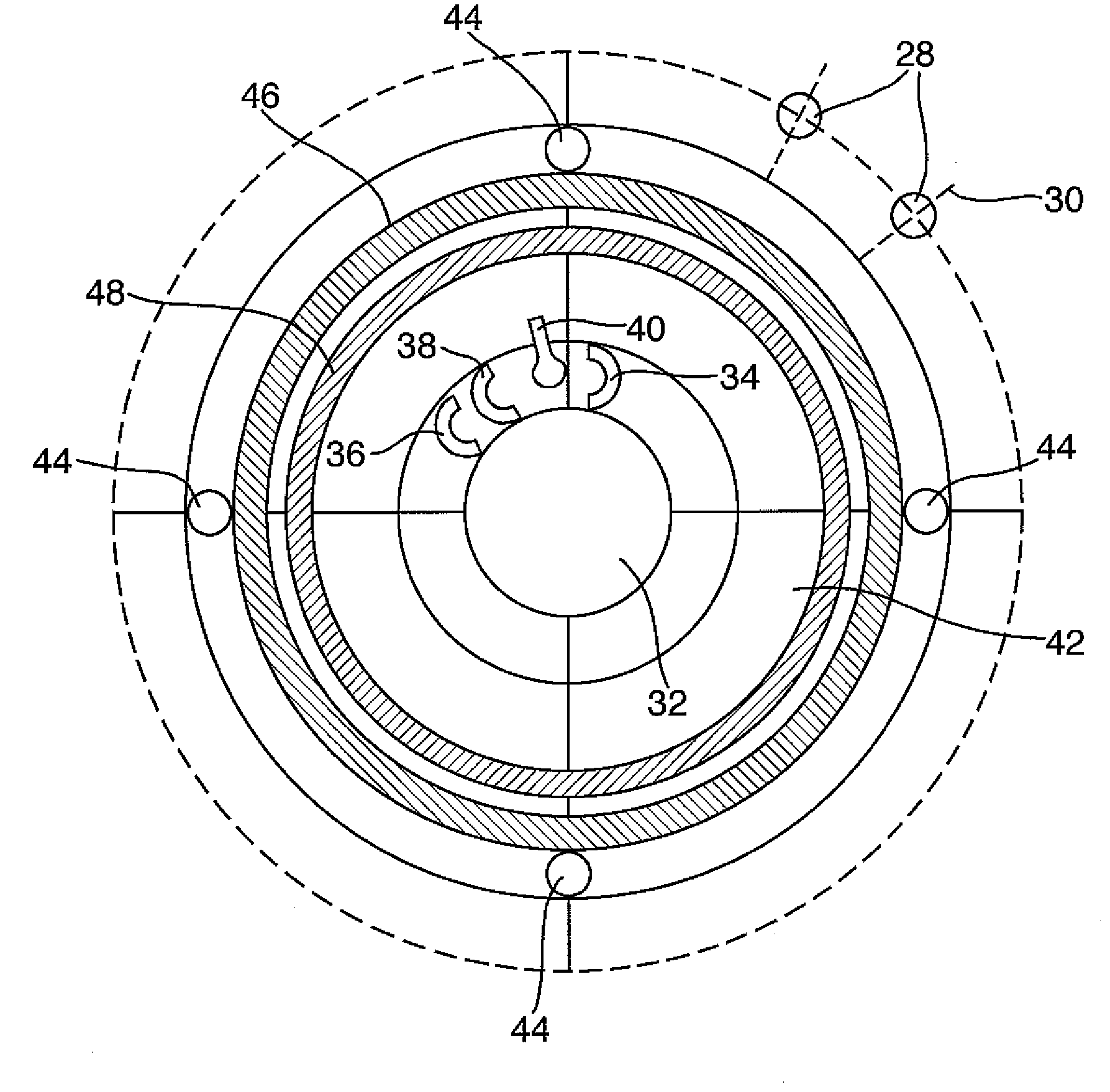
[0033]In a third aspect of the present invention there is a failsafe blade feather apparatus including a blade pitch angle regulator and an adjacent structure, the adjacent structure having at least one magnet connected thereto; the blade feather arrangement further having at least one plunger apparatus, the plunger apparatus connected to the blade pitch angle regulator and including a magnet, the plunger apparatus having retracted and deployed configurations wherein the retracted configuration is such that the magnet is spaced from the adjacent structure by sufficient distance to minimise the magnetic force therebetween, and the deployed configuration is such that the magnet is close enough to the adjacent structure to create a magnetic force therebetween; the plunger apparatus further including electrical retraction mechanism such that when current is applied, the plunger is held in the retracted configuration and when current is interrupted, the plunger is released into the deployed configuration. Advantageously, this apparatus is equally effective to slew the blades to feather when an electrical fault occurs as when a trip signal is sent to interrupt the current to the apparatus.

Problems solved by technology

This offers redundancy in the method.

Method used


Image

  • Blade pitch control
  • Blade pitch control
  • Blade pitch control

Examples


Embodiment Construction

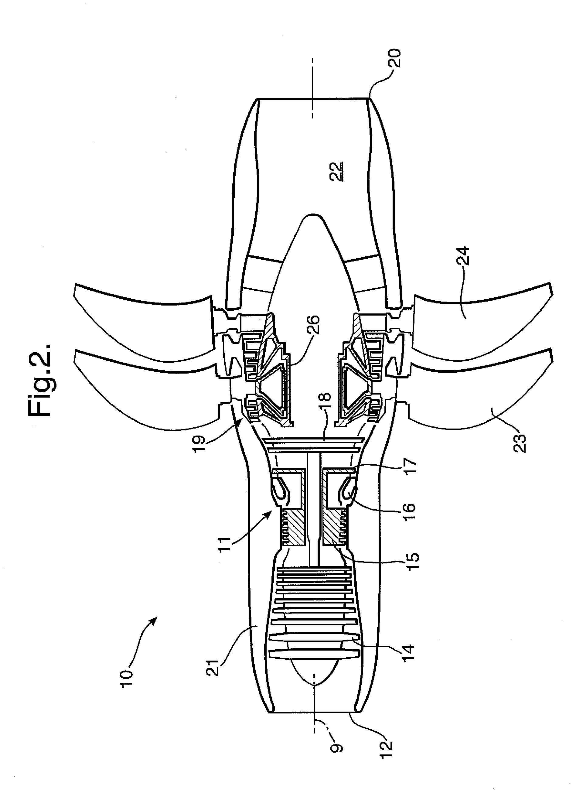
[0039]Referring to FIG. 2, a twin-spooled, contra-rotating propeller gas turbine engine is generally indicated at 10 and has a principal rotational axis 9. The engine 10 has a core engine 11 having, in axial flow series, an air intake 12, an intermediate pressure compressor 14, a high-pressure compressor 15, combustion equipment 16, a high-pressure turbine 17, intermediate pressure turbine 18, a free power (or low-pressure) turbine 19 and a core exhaust nozzle 20. A nacelle 21 generally surrounds the core engine 11 and defines the intake 12 and nozzle 20 and a core exhaust duct 22. The engine 10 also includes two contra-rotating propeller stages 23, 24 attached to and driven by the free power turbine 19 via shaft 26.

[0040]The gas turbine engine 10 works in a conventional manner so that air entering the intake 12 is accelerated and compressed by the intermediate pressure compressor 14 and directed into the high-pressure compressor 15 where further compression takes place. The compres...


PUM


Abstract

A method of controlling blade pitch angle, comprising the steps of:comparing demanded and measured blade pitch angle and calculating any difference therebetween,in a primary electrical control system, where there is a difference, applying torque to a blade pitch regulator to reduce the magnitude of the difference to zero, andin a secondary electrical control system, where the difference is greater than a pre-determined threshold, applying torque to a blade pitch regulator to reduce the magnitude of the difference to the threshold.Also an electrical system of blade pitch angle control for a set of blades comprising: primary and secondary electrical control systems, means for comparing demanded and measured blade pitch angle and calculating any difference therebetween, a look-up function having the difference as its input and outputting a required torque, and a torque regulator to apply the required torque to the set of blades.

Description

[0001]This application is entitled to the benefit of British Patent Application No. GB 0816637.3, filed on Sep. 12, 2008.FIELD OF THE INVENTION[0002]The present invention relates to electrical blade pitch control for rotor blades and is particularly relevant in relation to an engine comprising variable pitch propeller rotor blade stages.BACKGROUND OF THE INVENTION[0003]A known type of gas turbine engine, particularly for use in aircraft propulsion, is a propeller gas turbine engine or turboprop. This works in conventional form, whereby a core engine comprising compressors, combustion equipment and turbines drives one or more propeller rotor stages via a shaft from a free power, or low-pressure, turbine. The one or more propeller rotor stages may be situated at the front or rear of the engine, where front and rear are defined in terms of the direction of airflow through the engine. The propeller rotor blades extend radially outwardly to describe a larger diameter than the core engine...

Claims


Application Information

Patent Timeline
Patent Type & Authority Applications(United States)
IPC IPC(8): F01D7/00
CPCB64C11/306B64C11/44Y02T50/66B64D2027/005F01D7/00B64C11/48Y02T50/60
Inventor GAINFORD, DAVID MICHAELHOLT, JONATHAN EDMUNDGARNER, STEPHEN GRANVILLE
Owner ROLLS ROYCE PLC
Learn More