Scanning optical apparatus and image forming apparatus using the same

an optical apparatus and scanning technology, applied in the direction of electrographic process apparatus, instruments, printing, etc., can solve the problems of uneven distribution of light amount, difficulty in providing a surface of the imaging lens with antireflection coating, uneven plane illuminance, etc., to facilitate the manufacture of imaging optical systems, reduce the length of the apparatus in a direction of height, and improve the effect of quality

Inactive Publication Date: 2010-03-18
CANON KK
View PDF10 Cites 3 Cited by
  • Summary
  • Abstract
  • Description
  • Claims
  • Application Information

AI Technical Summary

Benefits of technology

[0021]The present invention aims at providing a scanning optical apparatus which is capable of forming a high quality image while manufacture of an imaging optical system is facilitated, a length of the apparatus in a direction of height is reduced, and unevenness of illuminance distribution (light amount distribution) on a surface to be scanned is reduced, and an image forming apparatus using the scanning optical apparatus.
[0038]According the present invention, there can be obtained a scanning optical apparatus which is capable of forming a high quality image while the manufacture of the imaging optical system is facilitated, the length of the apparatus in the direction of height is reduced, and the unevenness of illuminance distribution (light amount distribution) on the surface to be scanned is reduced.

Problems solved by technology

In the scanning optical apparatus configured by the plastic lens as described above, it is generally difficult to provide a surface of the imaging lens with antireflection coat.
For that reason, Fresnel reflection on the surface of the imaging lens is changed by a scanning angle, resulting in a tendency that unevenness of light amount distribution (image plane illuminance unevenness) occurs on the scanned surface.
However, a large amount of reflected light occurs from the lens surface because it is difficult to coat the lens surface of the plastic lens with an antireflection film.
That is, the unevenness of illuminance (unevenness of light amount distribution) occurs in a large amount.
However, the mirror has a reflection angle characteristic, and therefore the illuminance distribution on the scanned surface becomes uneven.
When the illuminance distribution on the scanned surface is uneven (when there is unevenness of light amount distribution), an image quality in forming an image is largely deteriorated.

Method used


Image

  • Scanning optical apparatus and image forming apparatus using the same
  • Scanning optical apparatus and image forming apparatus using the same
  • Scanning optical apparatus and image forming apparatus using the same

Examples


first embodiment

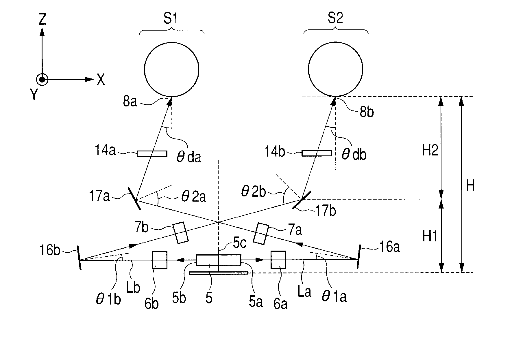
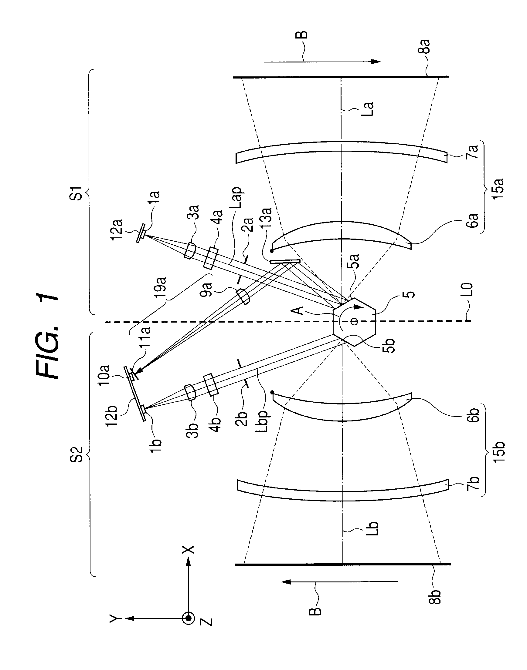
[0053]FIG. 1 is a cross-sectional view (main-scanning section view) illustrating a main portion of a scanning optical apparatus in a main-scanning direction according to a first embodiment of the present invention. FIG. 2 is a cross-sectional view (sub-scanning section view) illustrating a main portion of the scanning optical apparatus illustrated in FIG. 1 in a sub-scanning direction. In the following description, the main-scanning direction (Y-direction) is a direction (direction in which a light beam is deflected and reflected (deflected and scanned) by a deflecting unit) perpendicular to a rotation axis of the deflecting unit and an optical axis (X-direction) of an imaging optical system. The sub-scanning direction (Z-direction) is a direction parallel to the rotation axis of the deflecting unit. The main scanning section is a plane including the optical axis of the imaging optical system and the main-scanning direction. The sub-scanning section is a section including the optica...

second embodiment

[0182]A scanning optical apparatus according to a second embodiment of the present invention is described. The main scanning section of the second embodiment is identical with the cross-sectional view of the main portion (main scanning cross-sectional view) of the scanning optical apparatus in the main-scanning direction in the first embodiment illustrated in FIG. 1. Further, the sub-scanning section is identical with the sub-scanning cross-sectional view in the first embodiment illustrated in FIG. 2.

[0183]In this embodiment, a difference from the above-mentioned first embodiment resides in that the first mirrors 16a and 16b, and the second mirror 17a are provided with the common thin-film characteristics. Other arrangements and numeric values related to the optical characteristics in this embodiment are identical with those in the first embodiment.

[0184]FIGS. 6A and 6B illustrate the unevenness of image plane illuminance on the scanned surface in this embodiment, FIG. 6A illustrate...

third embodiment

[0203]A third embodiment of the present invention is described.

[0204]In this embodiment, a difference from the above-mentioned first embodiment resides in that a difference in the on-axis light beam incident angle between the two mirrors 17a and 17b closest to the scanned surface in the opposed two optical paths is further increased, and the height H is further reduced.

[0205]FIG. 7 is a diagram illustrating a sub-scanning section of a scanning optical apparatus according to a third embodiment of the present invention. Other arrangements and numeric values related to the optical characteristics in this embodiment are identical with those in the first embodiment.

[0206]In this embodiment, the on-axis light beam incident angles Θ2a(°) and Θ2b(°) of the two mirrors (second mirrors 17a and 17b) closest to the scanned surface in the opposed two optical paths are changed from those in the first embodiment.

[0207]As the real design values, the on-axis light beam incident angle Θ2a(°) of the s...


PUM


Abstract

Provided is a scanning optical apparatus capable of forming a high quality image while manufacture of an imaging optical system is facilitated, a length of the apparatus in a direction of height is reduced, and unevenness of illuminance distribution (light amount distribution) on a scanned surface is reduced. The scanning optical apparatus includes a single deflecting unit which deflects respective light beams from multiple light source units toward multiple scanned surfaces by different deflection surfaces, multiple incident optical systems each disposed in each light source unit, multiple optical systems which image the respective light beams on the multiple scanned surfaces, and multiple optical path changing units disposed in the respective optical paths between the single deflecting unit and the multiple scanned surfaces. A thin-film characteristic of each of the optical path changing units is different between the respective optical paths.

Description

BACKGROUND OF THE INVENTION[0001]1. Field of the Invention[0002]The present invention relates to an optical scanning apparatus and an image forming apparatus using the same. The present invention is suitable for an image forming apparatus such as a laser beam printer, a digital copying machine, or a multifunction printer, which adopts an electrophotography process.[0003]2. Description of the Related Art[0004]Up to now, a scanning optical apparatus is used for an image forming apparatus such as a laser beam printer (LBP), a digital copying machine, or a multifunction printer. In the scanning optical apparatus, a light beam (laser beam) optically modulated and output from a light source unit according to an image signal is periodically deflected by a deflector (an optical deflector) configured by, for example, a rotary polygon mirror.[0005]The deflected light beam is focused on a photosensitive recording medium (photosensitive drum) surface in the form of a spot by means of an imaging...

Claims


Application Information

Patent Timeline
Patent Type & Authority Applications(United States)
IPC IPC(8): G03G15/04
CPCB41J2/473G02B26/123G03G15/326G03G15/0435H04N1/1135H04N1/12H04N1/506G03G2215/0404
Inventor NAITO, YUUTA
Owner CANON KK
Why Eureka
Try Eureka