System and method of contouring a target area

Active Publication Date: 2010-03-04
TOMOTHERAPY INC
View PDF99 Cites 57 Cited by
  • Summary
  • Abstract
  • Description
  • Claims
  • Application Information

AI Technical Summary

Benefits of technology

[0004]In general, current radiation therapy planning software systems do not allow a user to interactively draw contours around a tumor that conform to other structures. Once a contour has been drawn around the tumor, the user can manually expand or contract the contour, but the user cannot automatically limit or conform the expansion or contraction of the contour while drawing. In many cases, the user must manually etch the margin as they draw. Further, the contour can be copied into other image views but the contours would need to be manually adjusted or translated to maintain the shape and size of the margins. In addition, the copying and translation must be done slice by slice, dramatically increasing the overall time it takes to proceed with planning the treatment and making the planning process much more complex.
[0005]The present invention provides a new workflow in 2D contouring and allows the user to maintain a minimum distance away (in 3D) from other structures. More specifically, the invention provides a means by which the user can rapidly define a series of contours that conform to the shape of one or more existing contours (or targets or structures) with user-specified margin limits between the new contour and the existing contours.
[0006]In one aspect of the invention, the contouring tool allows the user to draw a contour by beginning with a fixed shape and as the user draws out that shape to conform to the target or structure on the image, the tool automatically adjusts the shape (i.e., adjusts the contour) to maintain a predetermined set of margins. The user can input one or more limits defining a perimeter or margin around a structure to prevent a contour from infringing upon the defined perimeter or margin. For example, the user can specify a perimeter of 2 mm around the heart, 3 mm around the skin, and 5 mm around the spinal cord to prevent a contour of a portion of the lung to infringe upon those perimeters. The software-based contouring tool maintains the defined set of margins in real time as the user applies the basic contour shape to the lung area. Then, the user can copy the contours onto every image slice in a different view (i.e., in a 3D image set) and the margins will be maintained during the copying process.
[0007]In one embodiment, the invention provides a method of contouring an image. The method includes acquiring an image of a patient; identifying a perimeter to be maintained from a first structure in the image; applying a contour on the image at least partially around a second structure; and limiting the contour of the second structure in substantially real-time to not infringe the perimeter of the first structure.
[0008]In another embodiment, the invention provides a method of contouring an image. The method includes displaying an image having a plurality of views of a patient on a computer screen; identifying a perimeter to be maintained from a first structure in the image; applying a contour at least partially around a second structure in one of the views of the image in a first maneuver with a computer peripheral; applying the contour to a second one of the views of the image with a second consecutive maneuver of the computer peripheral; and translating the contour onto the second one of the views of the image while limiting the contour to the second structure to not infringe the perimeter of the first structure.

Problems solved by technology

In general, current radiation therapy planning software systems do not allow a user to interactively draw contours around a tumor that conform to other structures.
Once a contour has been drawn around the tumor, the user can manually expand or contract the contour, but the user cannot automatically limit or conform the expansion or contraction of the contour while drawing.
In addition, the copying and translation must be done slice by slice, dramatically increasing the overall time it takes to proceed with planning the treatment and making the planning process much more complex.

Method used


Image

  • System and method of contouring a target area
  • System and method of contouring a target area
  • System and method of contouring a target area

Examples


Embodiment Construction

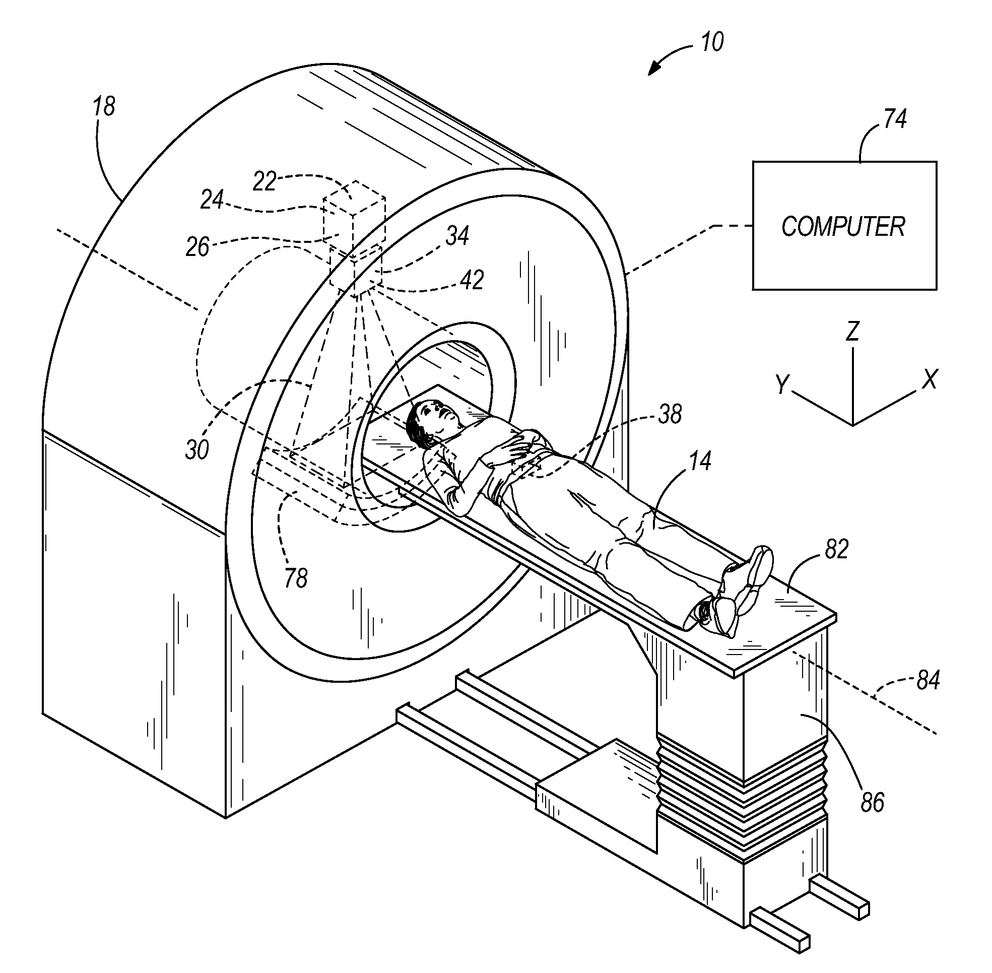
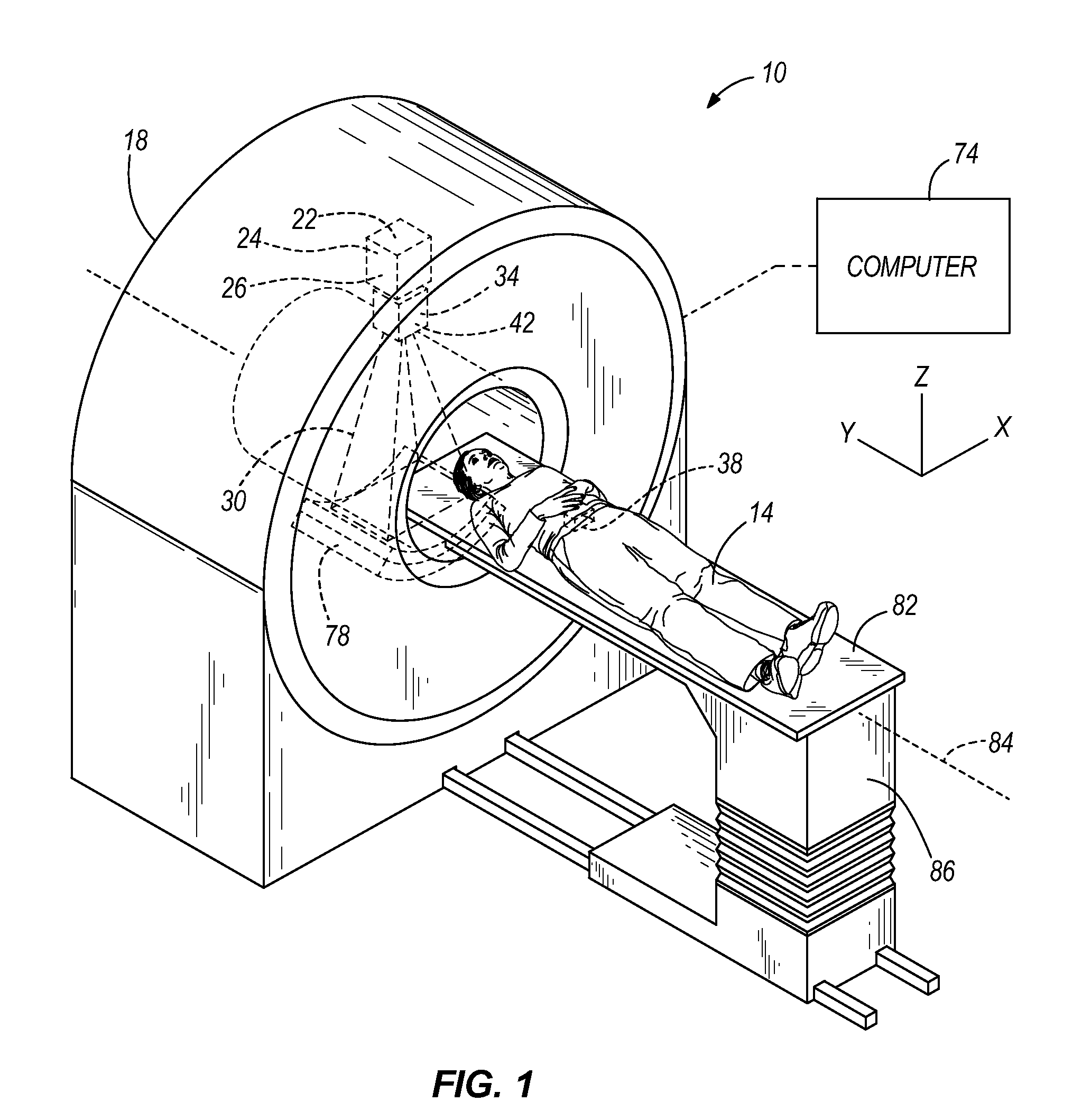
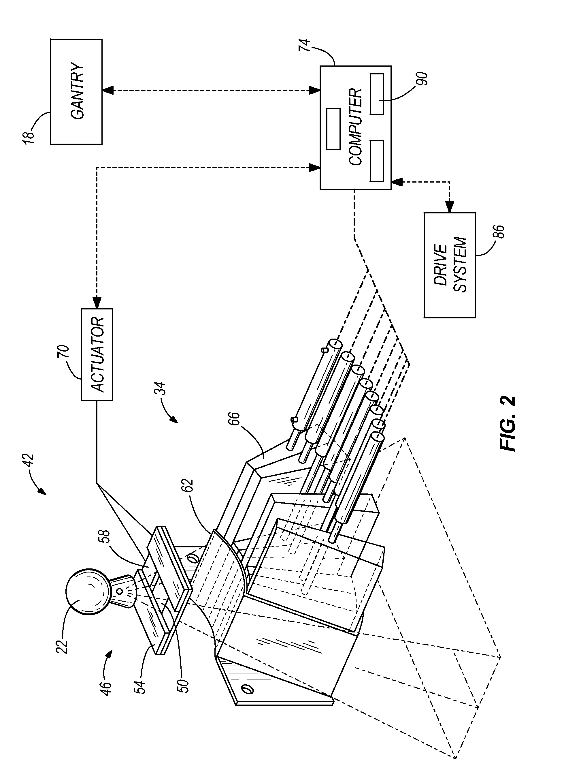
[0019]Before any embodiments of the invention are explained in detail, it is to be understood that the invention is not limited in its application to the details of construction and the arrangement of components set forth in the following description or illustrated in the following drawings. The invention is capable of other embodiments and of being practiced or of being carried out in various ways. Also, it is to be understood that the phraseology and terminology used herein is for the purpose of description and should not be regarded as limiting. The use of “including,”“comprising,” or “having” and variations thereof herein is meant to encompass the items listed thereafter and equivalents thereof as well as additional items. Unless specified or limited otherwise, the terms “mounted,”“connected,”“supported,” and “coupled” and variations thereof are used broadly and encompass both direct and indirect mountings, connections, supports, and couplings.

[0020]Although directional referenc...


PUM


Abstract

A two-dimensional contouring tool that allows a user to maintain a minimum distance away (in 3D) from other structures. The contouring tool allows the user to rapidly define a series of contours that conform to the shape of one or more existing contours (or targets) with user-specified margin limits between the new contour and the existing contours (or targets).

Description

RELATED APPLICATIONS[0001]This application claims priority to U.S. Provisional Patent Application No. 61 / 092,512, filed on Aug. 28, 2008, the entire contents of which are incorporated herein by reference.BACKGROUND OF THE INVENTION[0002]Radiation therapy has improved the lives of many patients who are battling cancer. Radiation therapy generally includes a series of treatments that specifically targets a cancerous tumor or other structure within the patient's body. Due to the precision required in applying the radiation to a particular area without affecting otherwise healthy tissue, radiation therapy planning software systems have been developed to better pinpoint the delivery of radiation.[0003]In general, the current process of contouring a tumor to identify where the radiation is to be applied is mostly manually and is very time consuming. In addition, applying the contour from one image to another image requires further manual adjustments, thus dramatically increasing the time ...

Claims


Application Information

Patent Timeline
IPC IPC(8): G09G5/00G16H20/40G16H30/40
CPCA61B5/055G06T2210/41A61B6/037A61B6/06A61N5/103A61N5/1042A61N2005/1074G06T7/0083G06T7/0091G06T19/00G06T2207/20036G06T2207/20104G06F19/321G06F19/3481A61B6/032G06T7/12G06T7/155G16H30/40G16H20/40
Inventor MENNINGEN, KEVIN S.GERING, DAVID T.RUCHALA, KENNETH J.
Owner TOMOTHERAPY INC
Why Eureka
Try Eureka