
Cutting tool with water injection to the cutting bit shank

a cutting tool and cutting bit technology, applied in the field of tools and tool assemblies, can solve the problems of premature failure of the cutting bit, abrasion and wear of the cutting tool and any other components, and eventual failure of the cutting tool, so as to promote free rotation

Inactive Publication Date: 2010-03-04
KENNAMETAL INC
View PDF19 Cites 20 Cited by
  • Summary
  • Abstract
  • Description
  • Claims
  • Application Information

AI Technical Summary

Benefits of technology

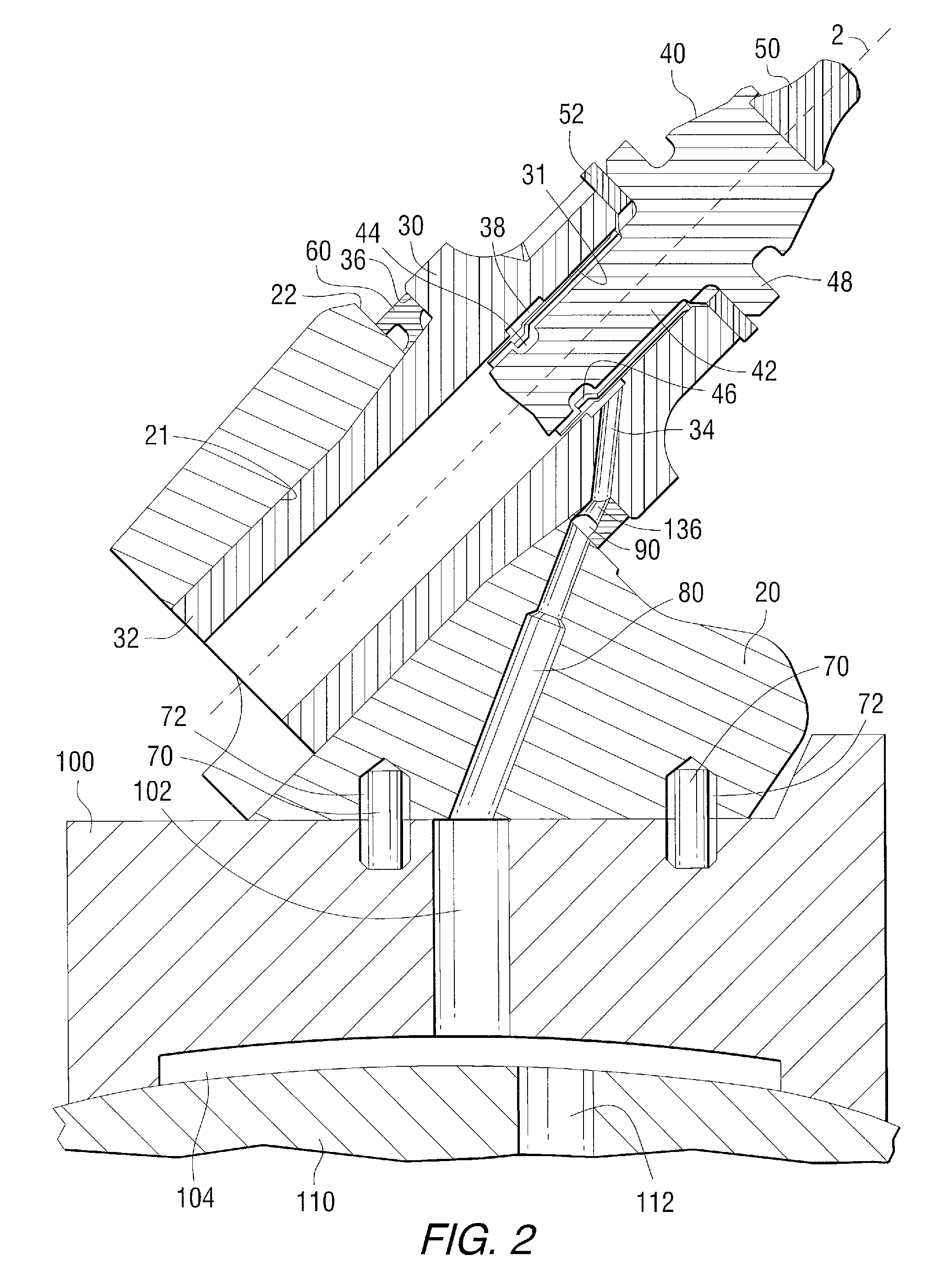
[0005]The present invention provides a cutting tool assembly including a support block, wear sleeve and cutting but which lubricates an interface of the cutting bit and the wear sleeve to promote even wear of the cutting bit thereby deterring premature failure of the cutting bit. A seal between the support block and the wear sleeve allows the fluid to pass from a passage in the support block to a passage in the wear sleeve. The wear sleeve passage discharges into a bore of the wear sleeve which holds a shank of the cutting bit. The fluid lubricates the space between the shank of the cutting bit and the bore of the wear sleeve. The lubrication promotes free rotation of the shank of the cutting bit within the bore of the wear sleeve.

Problems solved by technology

The continual collision of cutting pick and material being removed causes abrasion and wear of the cutting tool and any other components mounted on or near the support block.
The wear leads to eventual failure of the tool necessitating downtime of the associated equipment so the worn parts can be replaced.
It is a common occurrence for the cutting bits to seize within the bore preventing free rotation of the cutting bit and causing premature failure of the cutting bit.

Method used


Image

  • Cutting tool with water injection to the cutting bit shank
  • Cutting tool with water injection to the cutting bit shank
  • Cutting tool with water injection to the cutting bit shank

Examples


Embodiment Construction

[0014]For purposes of the following detailed description, it is to be understood that the invention may assume various alternative variations and step sequences, except where expressly specified to the contrary. In this application, the use of the singular includes the plural and plural encompasses singular, unless specifically stated otherwise. In addition, in this application, the use of “or” means “and / or” unless specifically stated otherwise, even though “and / or” may be explicitly used in certain instances.

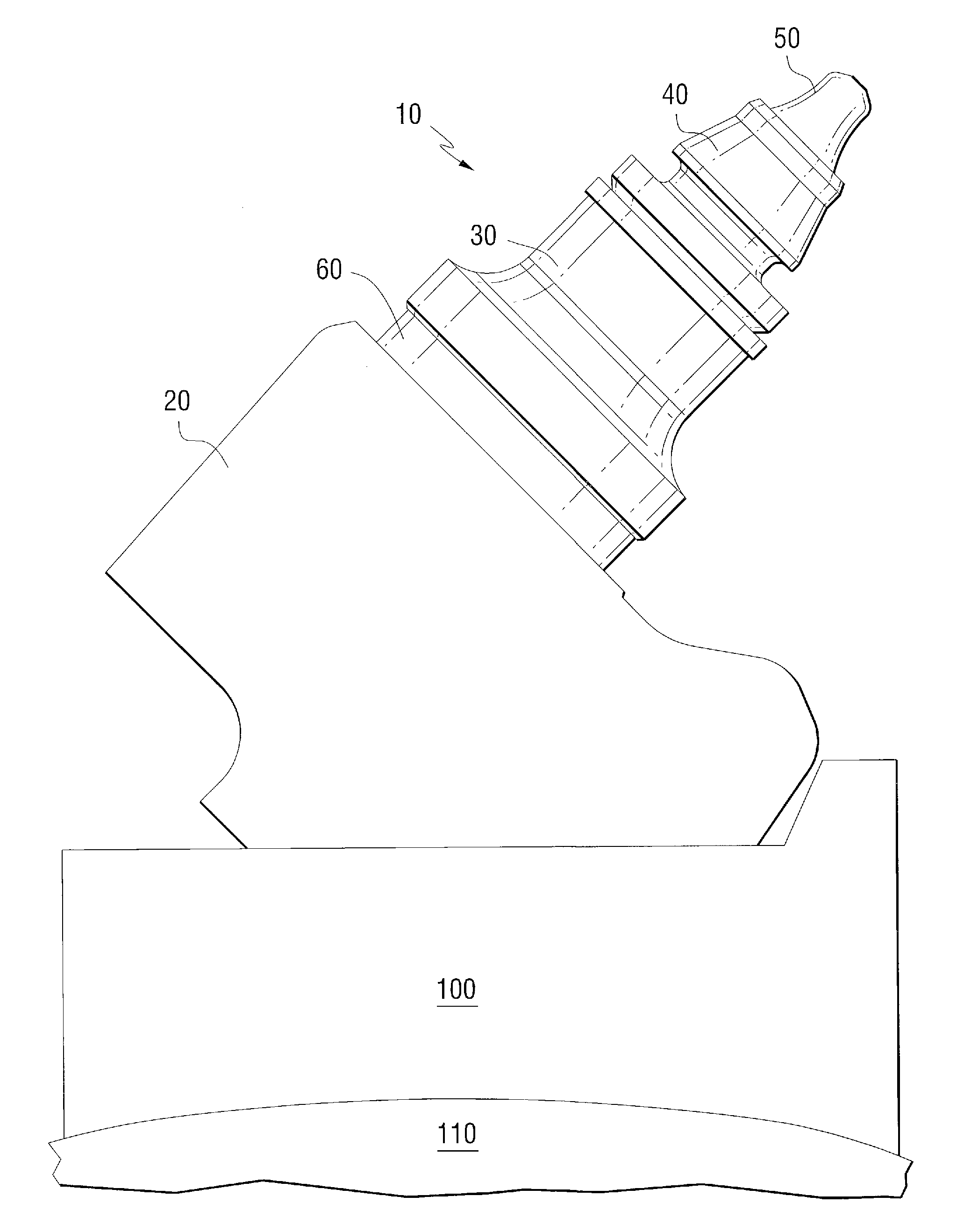
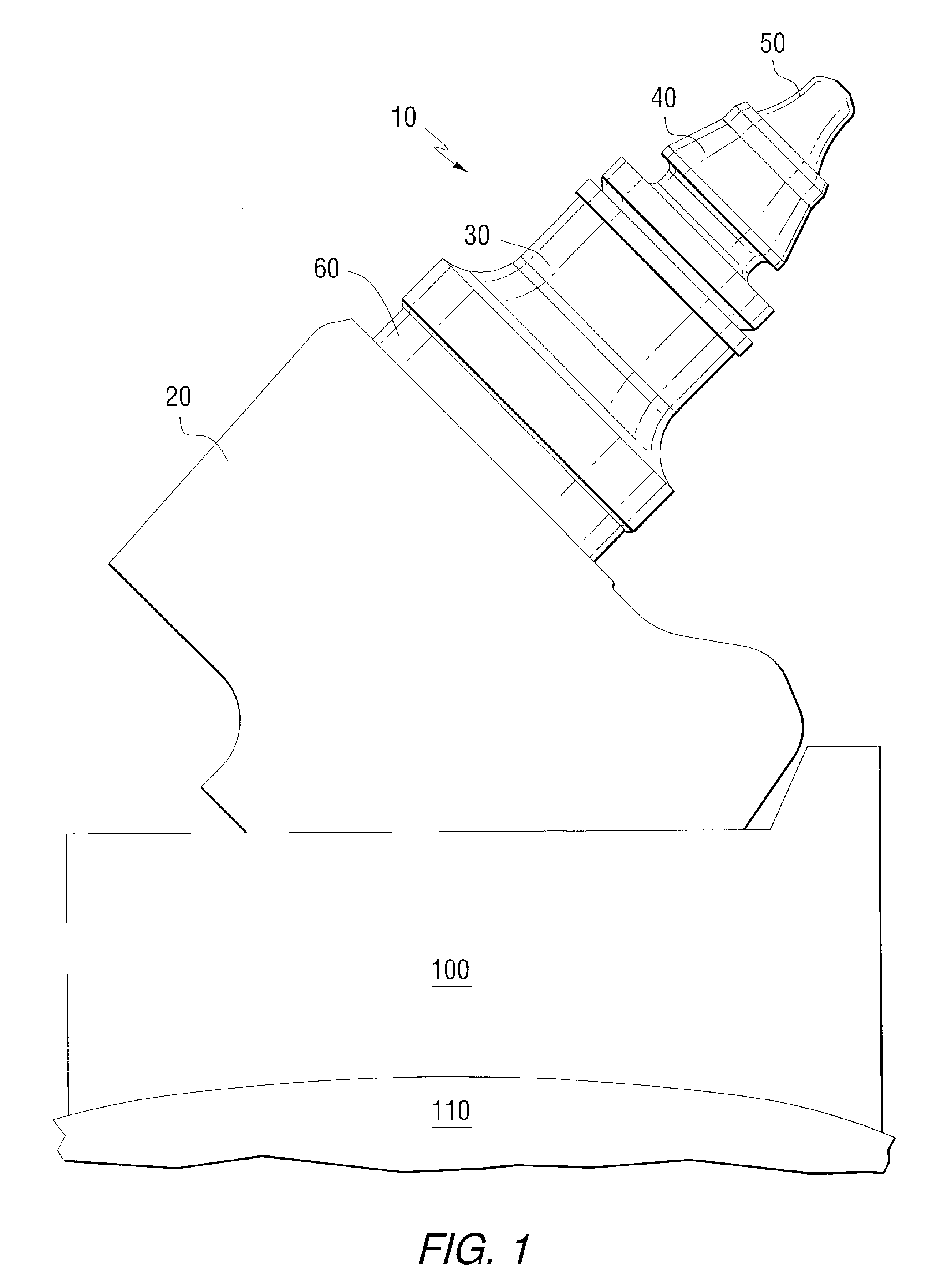
[0015]Referring now to FIG. 1, a cutting tool assembly 10 is shown according to one embodiment of the present invention. A support block 20 is structured and arranged to hold a wear sleeve 30. The wear sleeve 30, in turn, holds a cutting bit 40 which may have a hardened insert 50 at its tip. The hardened insert 50 often comprises a material such as cemented tungsten carbide, polycrystalline diamond or other suitable material. The supporting block 20 may be mounted on a pedesta...


PUM


Abstract

A cutting tool assembly mounted on a rotating drum and having a base block, a wear sleeve and a cutting bit wherein a seal is located between the base block and wear sleeve is disclosed. A fluid passage spans from the rotating drum to a discharge location between the wear sleeve and the shank of the cutting bit. The fluid lubricates the shank of the cutting bit and bore of the wear sleeve allowing the cutting bit to rotate freely within the wear sleeve. Rotation of the cutting bit promotes even wear and long life of the bit.

Description

FIELD OF THE INVENTION[0001]The present invention relates to tools and tool assemblies for mining and construction applications and, more particularly, is concerned with prolonging the life of the cutting tools in these applications.BACKGROUND INFORMATION[0002]Cutting tool assemblies for such applications as mining or road milling typically comprise a cutting tool, rotatably mounted within a support block. The support block in turn is mounted onto a drum, chain or other body, typically by welding, which in turn is driven by a suitable drive means. A number of such support blocks carrying cutting tools are mounted onto said drum to continually mine and remove material such as coal, rock, asphalt or concrete. The material removed by the cutting tool is pulverized by the cutting tool as each tip is rotated about the drum or chain into contact with the material. Some of the pulverized material collides against the support block and other cutting tool structure. The continual collision o...

Claims


Application Information

Patent Timeline
Patent Type & Authority Applications(United States)
IPC IPC(8): E21C25/10B23Q11/12
CPCE21C35/197E21C35/187
Inventor BEACH, WAYNE H.STIFFLER, STEPHEN P.HELSEL, ERIC P.KELLER, DONALD E.
Owner KENNAMETAL INC
Learn More