
Semiconductor device with isolation trench liner, and related fabrication methods

a technology of isolation trench and semiconductor, applied in the direction of semiconductor devices, basic electric elements, electrical equipment, etc., can solve the problems of affecting scaling, and reducing the service life of the devi

Active Publication Date: 2010-03-04
CHENGDU HAIGUANG INTEGRATED CIRCUIT DESIGN CO LTD
View PDF10 Cites 24 Cited by
  • Summary
  • Abstract
  • Description
  • Claims
  • Application Information

AI Technical Summary

Benefits of technology

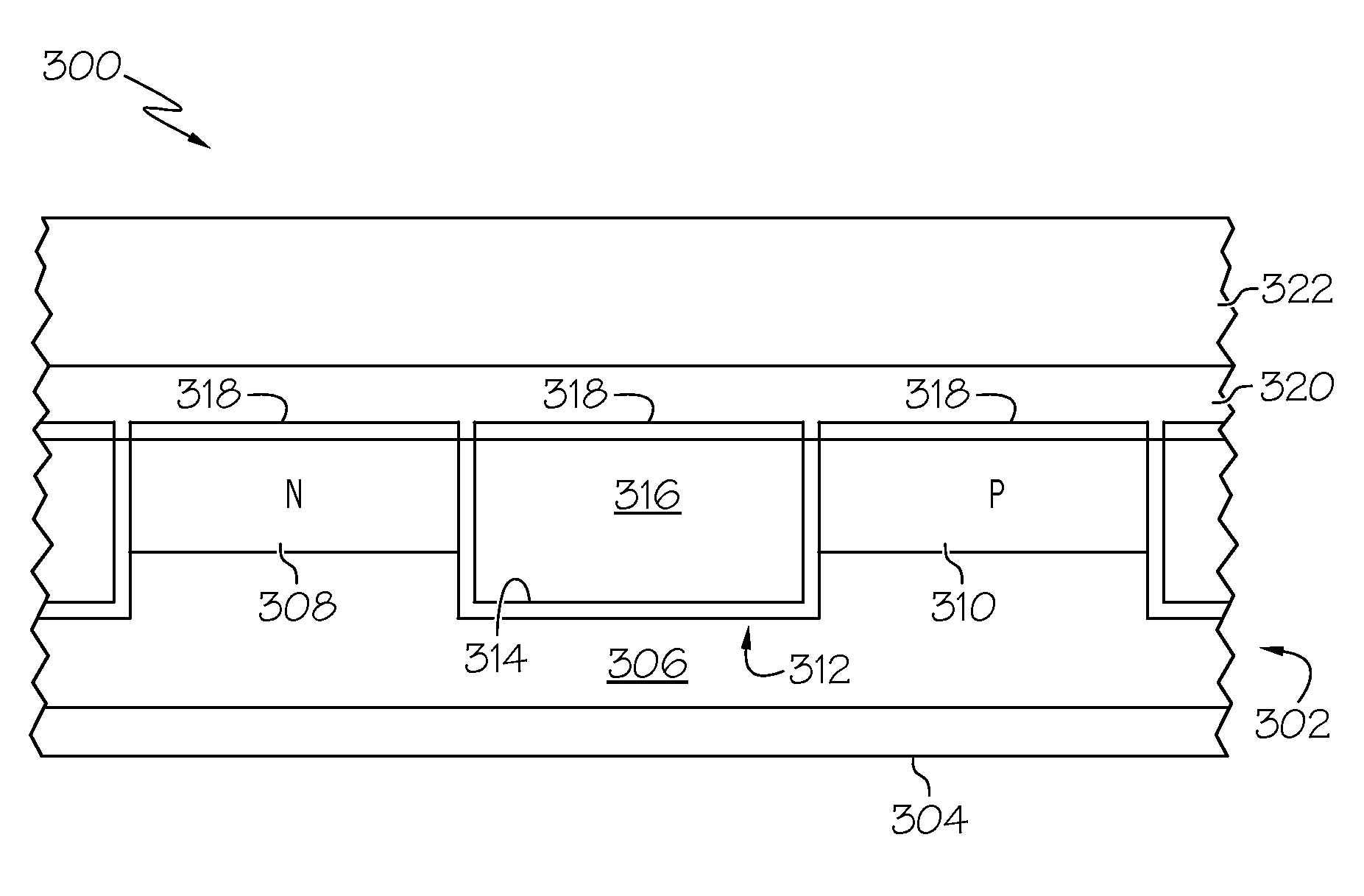
[0006]A method of manufacturing a semiconductor device structure is provided. The method begins by providing a substrate having semiconductor material. An isolation trench is formed in the semiconductor material, and the trench is lined with a liner material that substantially inhibits formation of high-k material thereon. The lined trench is filled with an insulating material, over which is formed a layer of high-k gate material. The high-k gate material is formed such that it overlies at least a portion of the insulating material and at least a portion of the semiconductor material, and such that the layer of high-k gate material is divided by the liner material.
[0007]A semiconductor device is also provided. The semiconductor device includes a layer of semiconductor material having an active transistor region defined therein, an isolation trench formed in the layer of semiconductor material adjacent to the active transistor region, a trench liner lining the isolation trench, an insulating material in the lined trench, and a layer of high-k gate material overlying at least a portion of the insulating material and overlying at least a portion of the active transistor region. The layer of high-k gate material is divided by the trench liner.
[0008]Also provided is a shallow trench isolation method for a semiconductor device structure. This method begins by providing a semiconductor substrate having a layer of semiconductor material, a pad oxide layer overlying the layer of semiconductor material, and a pad nitride layer overlying the pad oxide layer. The method then forms an isolation trench in the semiconductor substrate by selective removal of a portion of the pad nitride layer, a portion of the pad oxide layer, and a portion of the layer of semiconductor material. A liner material is deposited in the isolation trench and on exposed portions of the pad nitride layer, wherein the liner material substantially inhibits nucleation of high-k material thereon. In addition, an insulating material is deposited over the liner material such that the insulating material fills the isolation trench.
[0009]This summary is provided to introduce a selection of concepts in a simplified form that are further described below in the detailed description. This summary is not intended to identify key features or essential features of the claimed subject matter, nor is it intended to be used as an aid in determining the scope of the claimed subject matter.

Problems solved by technology

Notably, devices with shorter channel region lengths are more susceptible to the width effect.
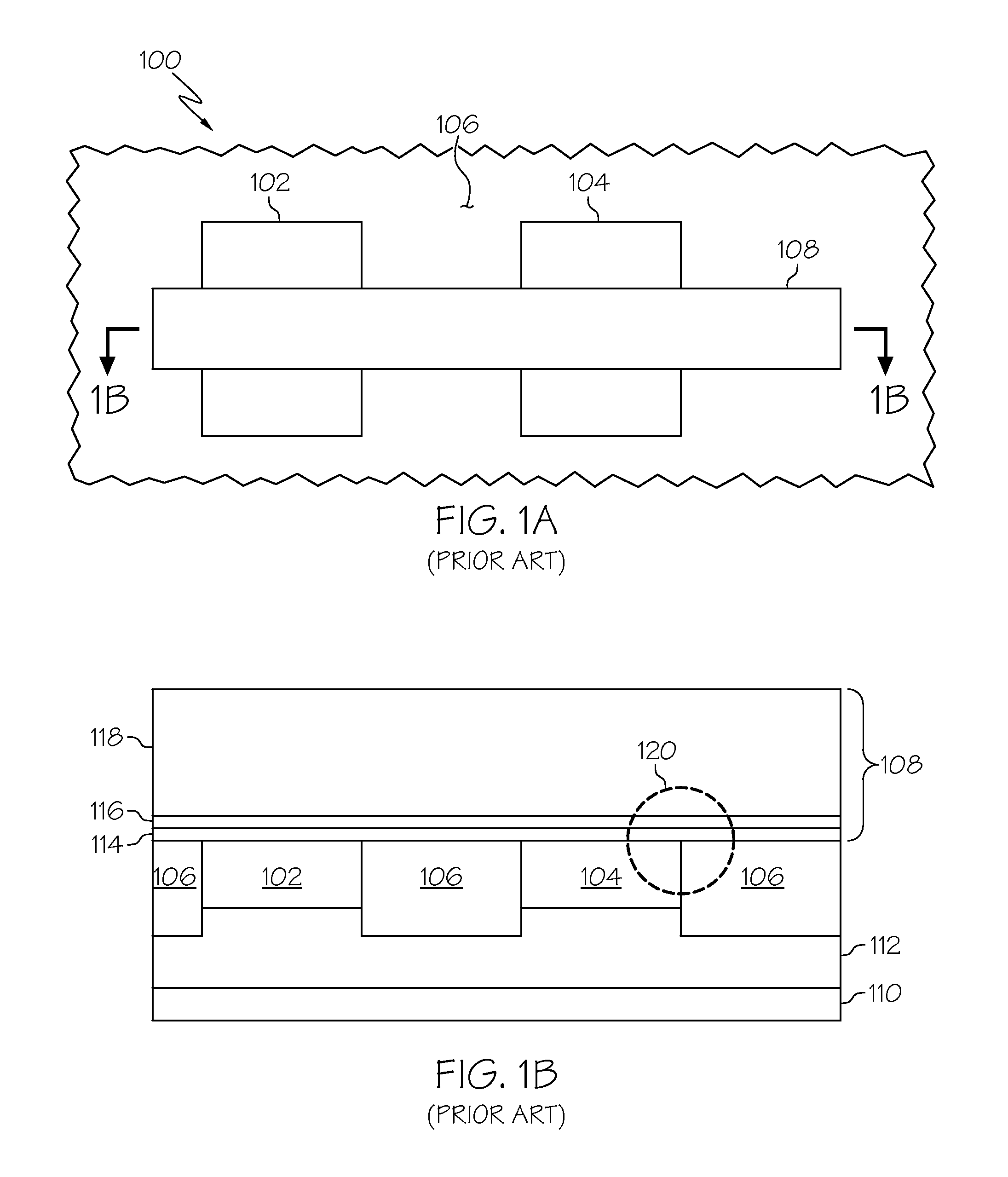
However, this adds control issues to dielectric deposition, and adversely impacts scaling.
However, excess nitridation degrades device performance and can adversely affect the threshold voltage of the device.
Unfortunately, oxygen scavenging metals have inherent control issues, which lead to excess variability in the process.
Such techniques require additional masking layers, and such techniques might violate existing controls and rules mandated by the particular manufacturing process node.
This approach is unproven, and it leads to significant process complexity for the isolation module and variability to subsequent process modules.

Method used


Image

  • Semiconductor device with isolation trench liner, and related fabrication methods
  • Semiconductor device with isolation trench liner, and related fabrication methods
  • Semiconductor device with isolation trench liner, and related fabrication methods

Examples


Embodiment Construction

[0015]The following detailed description is merely illustrative in nature and is not intended to limit the embodiments of the subject matter or the application and uses of such embodiments. As used herein, the word “exemplary” means “serving as an example, instance, or illustration.” Any implementation described herein as exemplary is not necessarily to be construed as preferred or advantageous over other implementations. Furthermore, there is no intention to be bound by any expressed or implied theory presented in the preceding technical field, background, brief summary or the following detailed description.

[0016]For the sake of brevity, conventional techniques related to semiconductor device fabrication may not be described in detail herein. Moreover, the various tasks and process steps described herein may be incorporated into a more comprehensive procedure or process having additional steps or functionality not described in detail herein. In particular, various steps in the manu...


PUM


Abstract

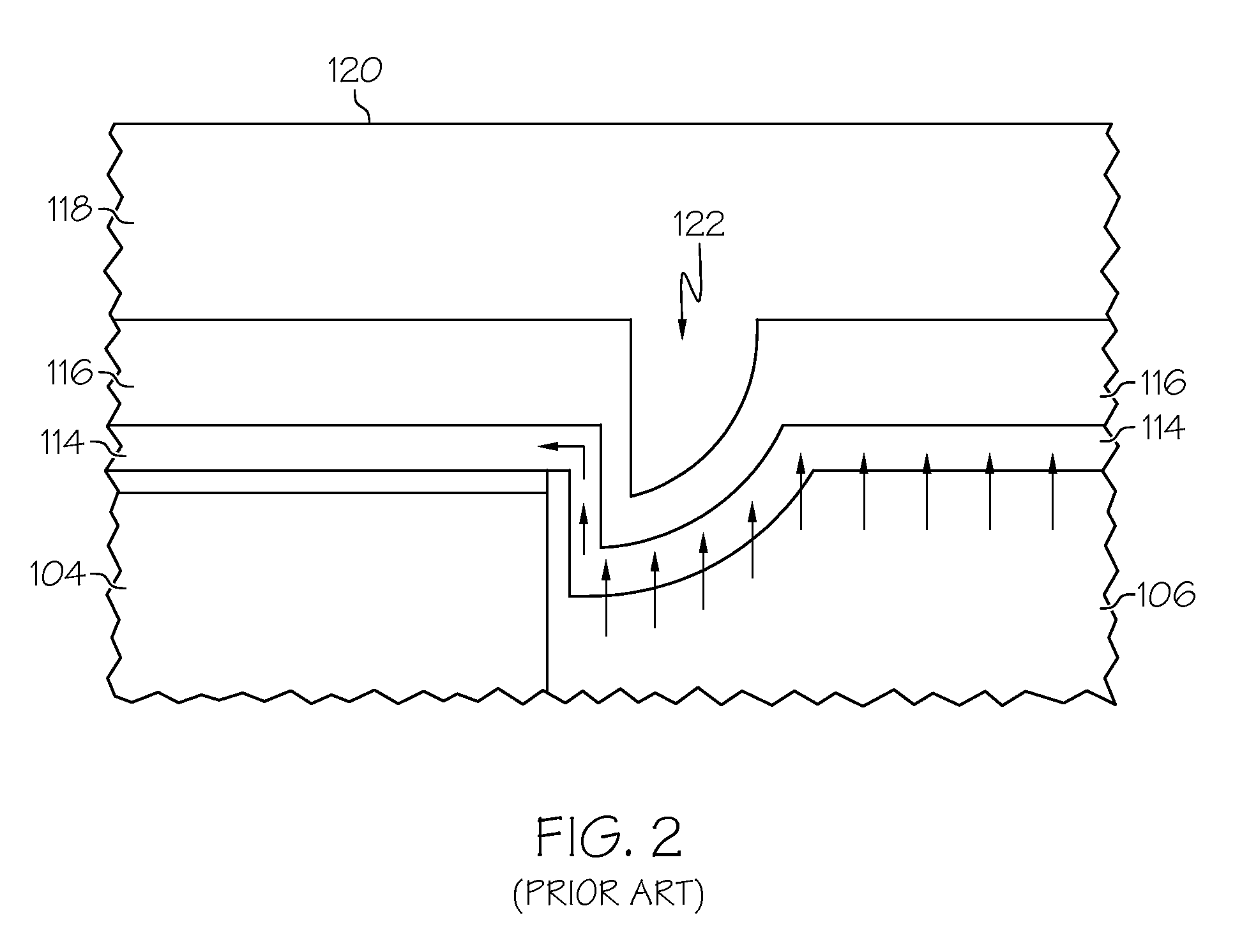
A method of manufacturing a semiconductor device is provided herein, where the width effect is reduced in the resulting semiconductor device. The method involves providing a substrate having semiconductor material, forming an isolation trench in the semiconductor material, and lining the isolation trench with a liner material that substantially inhibits formation of high-k material thereon. The lined trench is then filled with an insulating material. Thereafter, a layer of high-k gate material is formed over at least a portion of the insulating material and over at least a portion of the semiconductor material. The liner material divides the layer of high-k gate material, which prevents the migration of oxygen over the active region of the semiconductor material.

Description

TECHNICAL FIELD[0001]Embodiments of the subject matter described herein relate generally to semiconductor devices. More particularly, embodiments of the subject matter relate to the use of isolation regions between metal oxide semiconductor transistors.BACKGROUND[0002]The majority of present day integrated circuits (ICs) are implemented by using a plurality of interconnected field effect transistors (FETs), which may be realized as metal oxide semiconductor field effect transistors (MOSFETs or MOS transistors). A MOS transistor may be realized as a p-type device (i.e., a PMOS transistor) or an n-type device (i.e., an NMOS transistor). Moreover, a semiconductor device can include both PMOS and NMOS transistors, and such a device is commonly referred to as a complementary MOS or CMOS device. A MOS transistor includes a gate electrode as a control electrode that is formed over a semiconductor substrate, and spaced-apart source and drain regions formed within the semiconductor substrate...

Claims


Application Information

Patent Timeline
Patent Type & Authority Applications(United States)
IPC IPC(8): H01L29/00H01L21/76
CPCH01L21/76232H01L21/76264H01L21/76831H01L21/76841
Inventor CARTER, RICHARD J.KLUTH, GEORGE J.HARGROVE, MICHAEL J.
Owner CHENGDU HAIGUANG INTEGRATED CIRCUIT DESIGN CO LTD
Learn More