
Manufacturing Equipment and Manufacturing Method of Membrane Electrode Assembly

Inactive Publication Date: 2010-03-04
TOPPAN PRINTING CO LTD
View PDF0 Cites 44 Cited by
  • Summary
  • Abstract
  • Description
  • Claims
  • Application Information

AI Technical Summary

Benefits of technology

[0014]Moreover, as an area of the anode catalyst layer and cathode catalyst layer becomes large, the carrier film applied with tension may deform to contact with a concavities' bottom on the heat pressing roll. In other words, undesirable parts may be heated and pressed to form an anode catalyst layer and a cathode catalyst layer in undesirable regions by laminate. Since a sealing material is supposed to be arranged in these regions in a latter process, such catalyst layers formed in these regions on the electrolyte membrane cause sealing defects and thus the production efficiency decreases.
[0016]The present invention relates to a manufacturing method and manufacturing equipment of an MEA having a predetermined pattern of a laminated electrode catalyst layer on both sides of the electrolyte membrane. Specifically, the present invention provides a manufacturing method and manufacturing equipment of an MEA which has stable producing quality and a high level of productivity by making it possible to stably form an electrode catalyst layer having a predetermined area, shape and thickness, and to stably control process conditions of laminating the electrode catalyst layer onto both surfaces of an electrolyte membrane such as temperature, pressure and transfer rate of the carrier film.
[0025]The manufacturing equipment and the manufacturing method of the present invention make it possible to produce a large number of MEA continuously. In addition, since heats and pressures applied on both sides of the thin electrolyte membrane become the same in the present invention, in which an electrode catalyst layer formed on a carrier film and a thin electrolyte membrane simultaneously receive thermally laminating treatment, the electrolyte membrane is not damaged so that a generation of leakage is prevented.
[0027]In addition, since the electrode catalyst layer material is coated in only required regions on the carrier film so that almost all the electrode catalyst layer material used in the coating process is not wasted, a high level of material efficiency is achieved. Moreover, regions which are supposed to be used by a sealing material are not contaminated by the electrode catalyst layer material so that an increase in a defective ratio caused by a leakage can be prevented.

Problems solved by technology

In the case of the technique described in the patent document 1, however, the concavities and convexities are formed on a single heat pressing roll, which has a problem that a pressure distribution of the anode catalyst layer or the cathode catalyst layer formed on both surfaces of the electrolyte membrane is inclined to be uneven.
In addition, since shearing forces are applied to the electrolyte membrane around convexities' edges of the heat pressing roll, the fuel gas and the oxygen gas may leak.
In addition, the presence of convexities and concavities on the heat pressing roll means that the roll has an unfixed diameter.
As a result, a feed rate, a transfer rate or a winding rate etc. does not become constant, which prevents the anode catalyst layer or the cathode catalyst layer from being coated evenly on a respective carrier film and leads to an uneven coating thickness.
Since a sealing material is supposed to be arranged in these regions in a latter process, such catalyst layers formed in these regions on the electrolyte membrane cause sealing defects and thus the production efficiency decreases.

Method used


Image

  • Manufacturing Equipment and Manufacturing Method of Membrane Electrode Assembly
  • Manufacturing Equipment and Manufacturing Method of Membrane Electrode Assembly
  • Manufacturing Equipment and Manufacturing Method of Membrane Electrode Assembly

Examples


Embodiment Construction

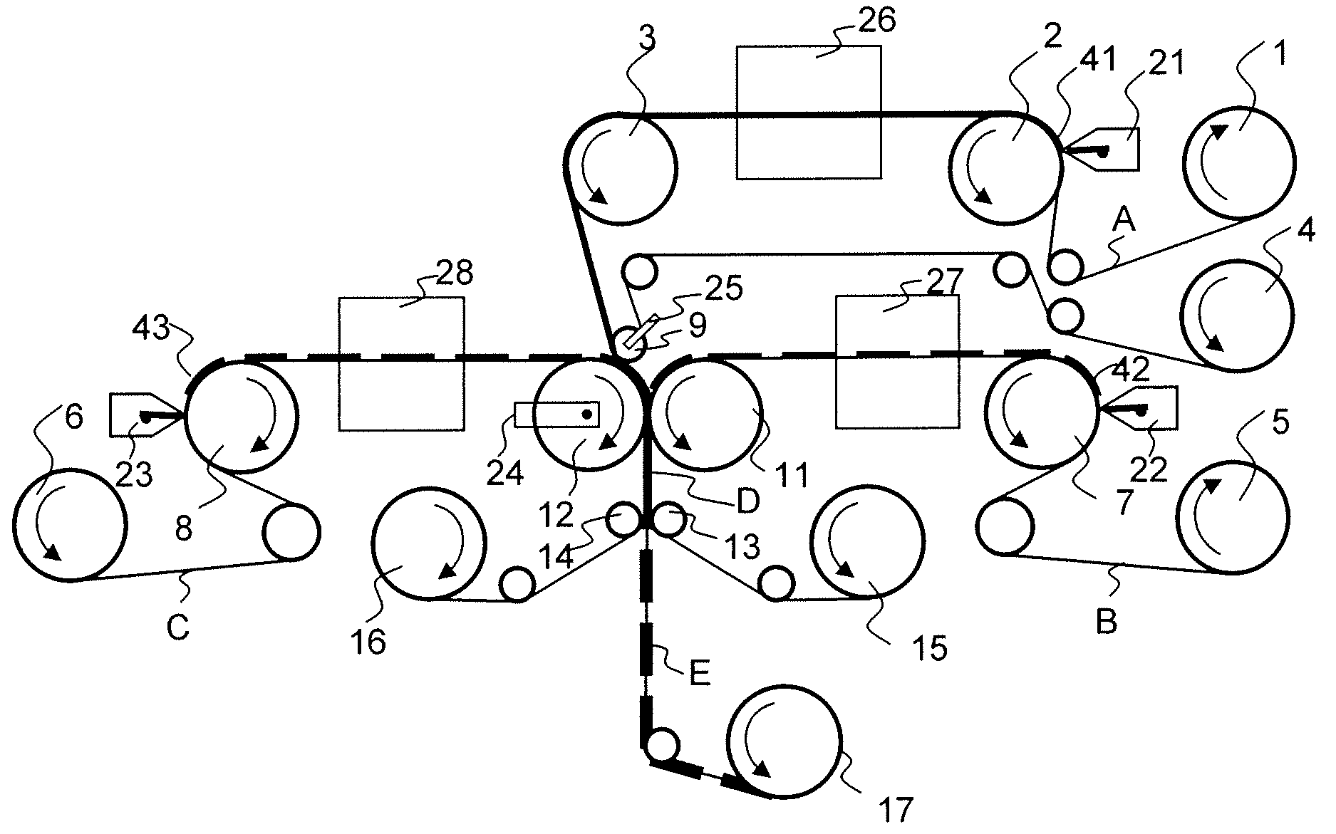
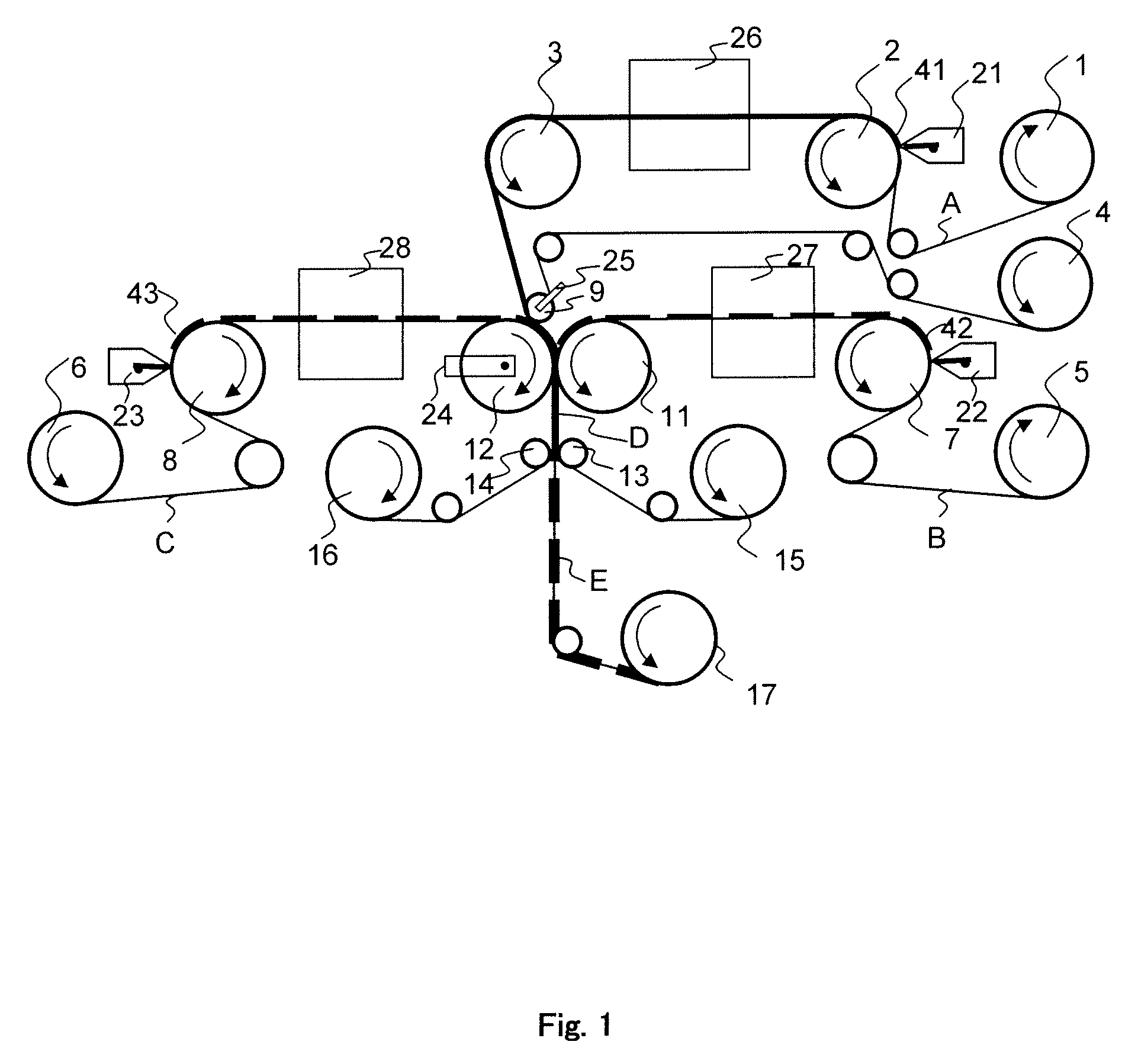
[0059]Referring to the figures, embodiments of the present invention will be described below. FIG. 1 illustrates an exemplary diagram of MEA manufacturing equipment of an embodiment of the present invention.

[0060]First, a carrier film A is wound off with a constant feed rate and a constant tension from a film feeding part 1. An electrolyte material 41 with a predetermined width and uniform thickness is coated on the carrier film A on a coating roll 2 by a coating means 21.

[0061]The carrier film A on which the electrolyte material 41 is coated is transferred into a drying oven 26. Then, the electrolyte material 41 is dried and an electrolyte membrane 41 is formed on the carrier film.

[0062]Meanwhile, a carrier film B and C are wound off respectively with a constant feed rate and a constant tension from film feeding parts 5 and 6 which are arranged facing each other, and electrode catalyst materials 42 and 43 are intermittently coated on the carrier films B and C on coating rolls 7 and...


PUM

PropertyMeasurementUnit
Lengthaaaaaaaaaa
Pressureaaaaaaaaaa

Abstract

The present invention provides a manufacturing method and manufacturing equipment which makes it possible to manufacture a fuel cell MEA (membrane electrode assembly) continuously and stably with a high level of precision. The present invention provides a manufacturing method of a fuel cell MEA which includes transferring three carrier films in belt shapes, coating an electrolyte membrane in predetermined regions on one of the carrier films, coating electrode catalyst layers intermittently in predetermined regions on the other two carrier films, drying the electrolyte and the electrode catalyst layers on the carrier films, laminating the electrolyte membrane onto an electrode catalyst layer on one of the carrier films with a pressure and peeling off and removing the carrier film of the electrolyte membrane, laminating the other electrode catalyst layer onto the electrolyte membrane laminated on the electrode catalyst layer with heat and a pressure, and peeling off the carrier films from the resultant laminated product of the electrolyte membrane and the electrode catalyst layers.

Description

CROSS REFERENCE TO RELATED APPLICATION[0001]This application is based on and claims the benefit of priority from the Japanese Patent Application number 2008-219399, filed on Aug. 28, 2008, the entire contents of which are incorporated herein by reference.BACKGROUND OF THE INVENTION[0002]1. Field of the Invention[0003]The present invention relates to a manufacturing method and manufacturing equipment which make it possible to fabricate a membrane electrode assembly (MEA) of a fuel cell having electrode catalyst layers on both (rear and front) surfaces of an electrolyte membrane with a high precision continuously and stably.[0004]2. Description of the Related Art[0005]A component which has electrode catalyst layers on both rear and front surfaces of a polymer electrolyte membrane and which is called a membrane electrode assembly (MEA) is used in a polymer electrolyte fuel cell. A heat pressing technique and a laminating technique are available as a forming method of the MEA.[0006]The ...

Claims


Application Information

Patent Timeline
IPC IPC(8): H01M4/04B32B37/14H01M4/88H01M8/02H01M8/10
CPCB32B37/025B32B37/153B32B38/164B32B2457/18H01M4/8814Y02E60/50H01M4/8835H01M4/8839H01M4/8882H01M4/8896H01M4/8828
Inventor MORI, HIDEKI
Owner TOPPAN PRINTING CO LTD
Learn More