Adaptive voltage bias methodology

a voltage bias and bias technology, applied in the field of adaptive voltage bias methodology, can solve the problems of not being satisfactory in all respects, unable to effectively minimize the power dissipation, and not being able to achieve the effect of minimizing the power dissipation

Inactive Publication Date: 2010-02-25
TAIWAN SEMICON MFG CO LTD
View PDF16 Cites 12 Cited by
  • Summary
  • Abstract
  • Description
  • Claims
  • Application Information

AI Technical Summary

Benefits of technology

[0004]Another one of the broader forms of an embodiment of the present invention involves an adaptive voltage bias control system. The system includes a frequency detector coupled with a logic circuit; an adaptive controller coupled with the frequency detector; a first vol...

Problems solved by technology

Power dissipation is a concern and challenge in integrated circuit (IC) designs and applications.
Although these approaches have been satisfactory for their intended purposes, they have not been satisfactory in all respects.
For example, the existing approaches may not eff...

Method used


Image

  • Adaptive voltage bias methodology
  • Adaptive voltage bias methodology
  • Adaptive voltage bias methodology

Examples


Embodiment Construction

[0007]It is to be understood that the following disclosure provides many different embodiments, or examples, for implementing different features of various embodiments. Specific examples of components and arrangements are described below to simplify the present disclosure. These are, of course, merely examples and are not intended to be limiting. In addition, the present disclosure may repeat reference numerals and / or letters in the various examples. This repetition is for the purpose of simplicity and clarity and does not in itself dictate a relationship between the various embodiments and / or configurations discussed.

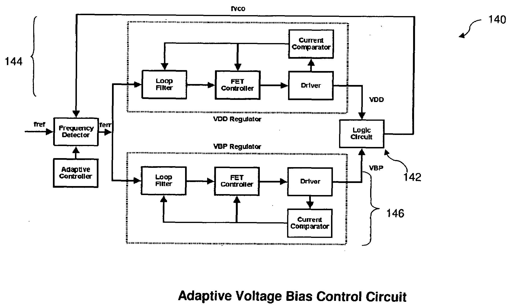
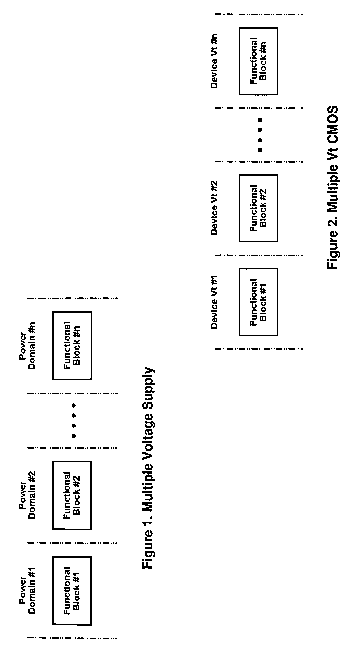
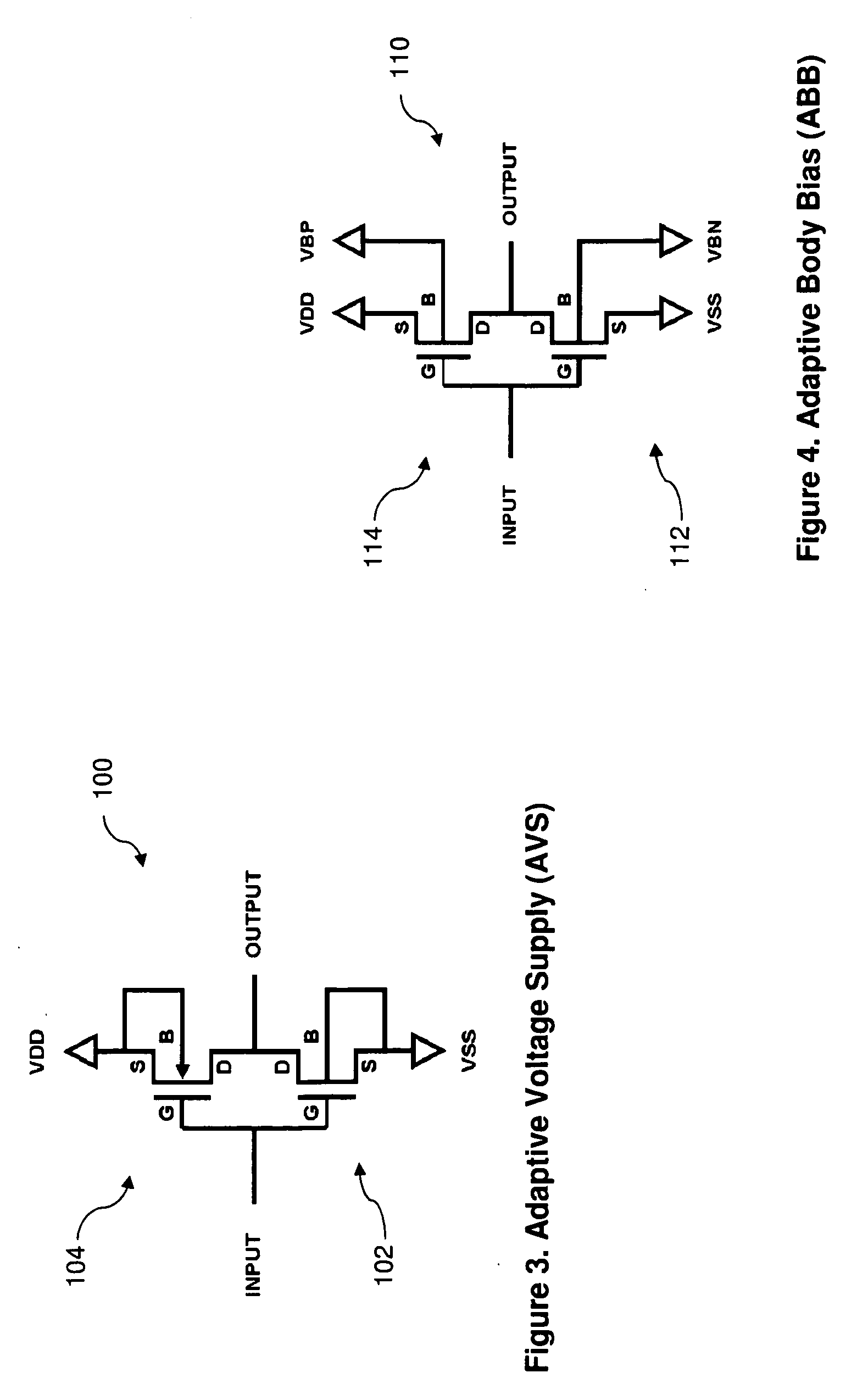
[0008]FIGS. 1 through 7 are schematic views of various integrated circuits for adaptive voltage bias constructed according to various aspects of the present disclosure in different embodiments. An adaptive voltage bias control system and a method for operating a logic circuit in an adaptive voltage bias are collectively described with reference to FIGS. 1 through 7.

[00...


PUM


Abstract

The present disclosure provides an integrated circuit. The integrated circuit includes a frequency detector coupled with a logic circuit; a supply voltage regulator coupled with the frequency detector and designed to provide an adaptive voltage supply to the logic circuit based on a frequency error from the frequency detector; and a substrate bias regulator coupled with the frequency detector and designed to provide an adaptive body bias voltage to the logic circuit based on the frequency error.

Description

PRIORITY DATA[0001]This application claims priority to Provisional Application Ser. No. 61 / 091,603, filed on Aug. 25, 2008, entitled “ADAPTIVE VOLTAGE BIAS METHODOLOGY,” the entire disclosure of which is incorporated herein by reference.BACKGROUND[0002]Power dissipation is a concern and challenge in integrated circuit (IC) designs and applications. Various approaches have been used to reduce the power dissipation. For example, dual power is used in integrated circuits to reduce the power dissipation. In existing technologies, a power reduction technique reduces either an active power (Multiple Voltage Supply) or leakage power (Mixed Vt). Moreover, due to smaller geometries with advanced processes, the circuit performance is more sensitive to the process variations. Although these approaches have been satisfactory for their intended purposes, they have not been satisfactory in all respects. For example, the existing approaches may not effectively minimize the power dissipation due to...

Claims


Application Information

Patent Timeline
IPC IPC(8): G05F3/02
CPCH03K19/0013
Inventor LAW, OSCAR M. K.THEI, KONG-BENGCHUANG, HARRY
Owner TAIWAN SEMICON MFG CO LTD
Why Eureka
Try Eureka