Motor driving apparatus

Active Publication Date: 2010-02-25
DYSON TECH LTD
View PDF16 Cites 73 Cited by
  • Summary
  • Abstract
  • Description
  • Claims
  • Application Information

AI Technical Summary

Benefits of technology

[0006]It is an object of the invention to provide motor driving apparatus which enables a cleaning appliance to maintain good cleaning performance throughout the useable run time of the battery. A further object of the invention is to provide motor driving apparatus which is able to supply a substantially constant voltage from a battery source to a motor in order to maintain substantially constant the cleaning performance of a handheld vacuum cleaner during the useable run time of the battery.
[0007]The invention provides motor driving apparatus for a cleaning appliance comprising a battery source and a power controller, the battery source being adapted and arranged to supply the power controller with an output having a first voltage, the first voltage decreasing as the battery source is discharged, and the power controller being adapted and arranged to modulate the output to produce a drive signal for driving a motor, the drive signal having a second voltage and a variable duty cycle, wherein the power controller is adapted and arranged to increase the duty cycle of the drive signal as the first voltage decreases in order to maintain the second voltage at a substantially constant average value per unit time. By providing the above arrangement, the motor can be supplied with a substantially constant voltage throughout the useable run time of the battery. When driving a motor forming part of a cleaning appliance, the above arrangement allows the motor to operate at a substantially constant speed throughout the useable run time of the battery, resulting in more consistent cleaning performance.
[0008]Further, the maximum available voltage supplied by the battery is useable by the motor during an “on” period of the duty cycle and no power is drawn from the battery during the “off” period of the duty cycle. Therefore, a substantially constant voltage can be supplied to the motor without the need to dissipate excess voltage across, for example, a variable resistor when the battery voltage is higher than the desired voltage. This results in greater efficiency and improved battery life. In addition, the arrangement of the present invention is cheaper and simpler than alternative arrangements such as switched mode power supplies. Preferably, the power controller is adapted and arranged to switch the motor off when the duty cycle reaches a pre-determined value. By providing such an arrangement, the power controller can determine whether the charge in the battery has reached the minimum value necessary to maintain the second voltage at a substantially constant average value per unit time. Operation beyond this point will result in the battery being unable to supply the voltage required to maintain the cleaning performance of the cleaning appliance. Therefore, it is desirable to switch the motor off at this point before the cleaning performance of the cleaning appliance is reduced. More preferably, the pre-determined value is 100%. When the duty cycle reaches 100%, power is being drawn continuously from the battery in order to maintain the required cleaning performance. Therefore, if the battery continues to be depleted the second voltage will drop below the minimum value necessary to maintain cleaning performance. Consequently, the power controller is arranged to switch the motor off before further charge is depleted from the battery and the cleaning performance is reduced.
[0010]Preferably, the first voltage is equal to the second voltage. By providing such an arrangement, there is no need to modify the amplitude of the voltage of the output from the battery when producing the drive signal to drive the motor. This eliminates the need for transformers or voltage regulators which may be bulky and inefficient.

Problems solved by technology

Operation beyond this point will result in the battery being unable to supply the voltage required to maintain the cleaning performance of the cleaning appliance.
Consequently, the power controller is arranged to switch the motor off before further charge is depleted from the battery and the cleaning performance is reduced.

Method used


Image

  • Motor driving apparatus
  • Motor driving apparatus
  • Motor driving apparatus

Examples


Embodiment Construction

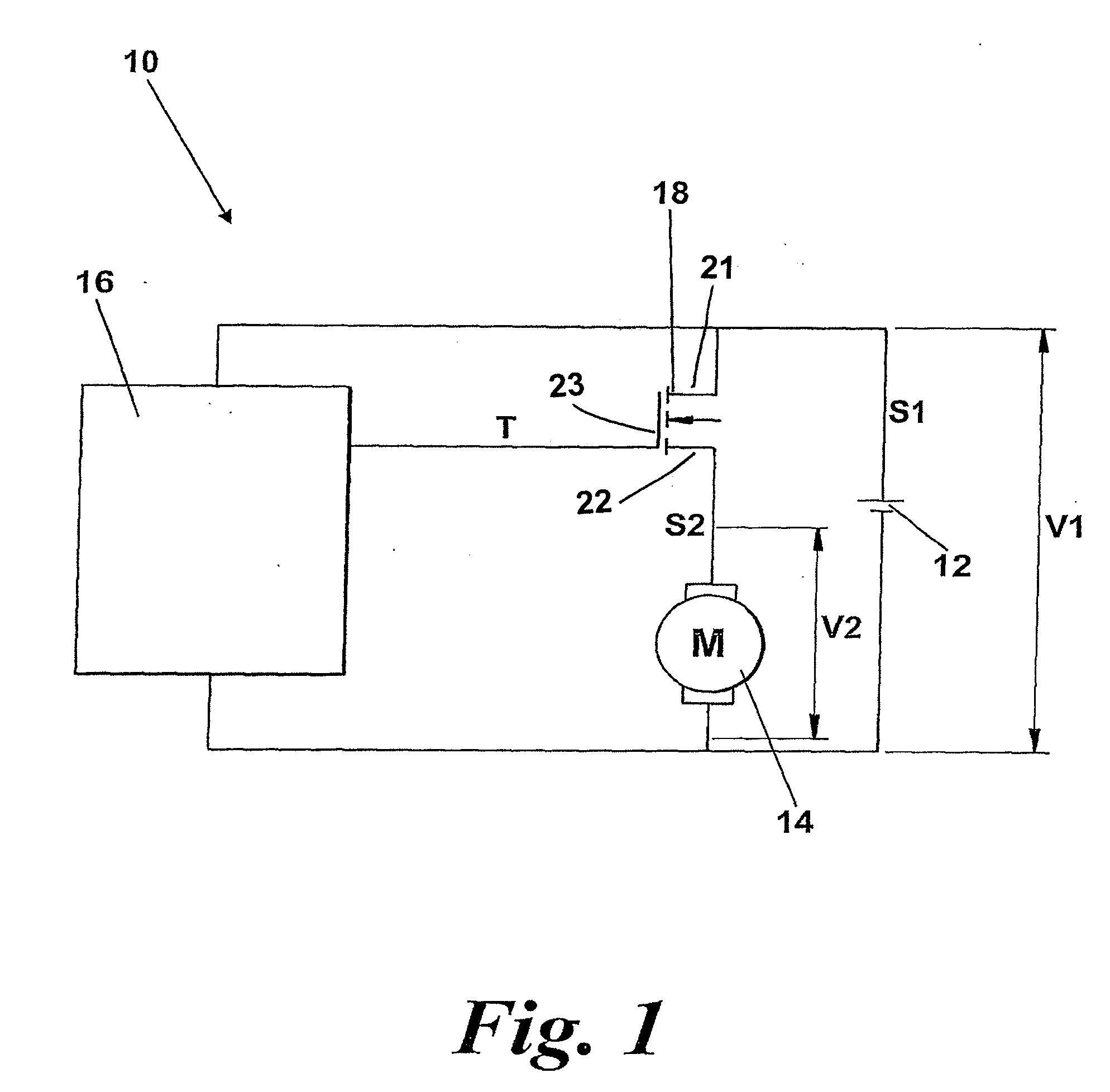
[0019]FIG. 1 shows a motor driving apparatus 10 according to the invention. The motor driving apparatus 10 comprises a rechargeable battery 12, a motor 14 and a power controller 16. The motor driving apparatus 10 further comprises a power Metal Oxide Field Effect Transistor (power MOSFET) 18 which is located in parallel with the battery 12 and in series with the motor 14. The power MOSFET 18 has a source, a drain and a gate (not shown) and functions as a switch between the positive and negative terminals of the battery 12.

[0020]The power controller 16 is connected to the gate of the power MOSFET 18. The gate can be switched in order to control the current flow between the source and the drain of the power MOSFET 18. The power controller 16 switches the gate using a timing signal T which has a frequency of 4 kHz and a duty cycle specified by the power controller 16. Under the control of the power controller 16, the timing signal T takes the form of a series of wave “packets” or pulse...


PUM


Abstract

A motor driving apparatus for a cleaning appliance includes a battery source and a power controller. The battery source supplies the power controller with an output having a first voltage which decreases as the battery source is discharged. The power controller modulates the output to produce a drive signal for driving a motor that has a second voltage and a variable duty cycle. The power controller increases the duty cycle of the drive signal as the first voltage decreases in order to maintain the second voltage at a substantially constant average value per unit time. By providing the above arrangement, the motor can be supplied with a constant voltage throughout the available run time of the battery. When forming part of a cleaning appliance having a motor, the above arrangement allows the motor to operate at a substantially constant speed throughout the run time of the battery.

Description

REFERENCE TO RELATED APPLICATIONS[0001]This application is a national stage application under 35 USC 371 of International Application No. PCT / GB2007 / 003379, filed Sep. 10, 2007, which claims the priority of United Kingdom Application No. 0618490.7, filed Sep. 20, 2006, the contents of which prior applications are incorporated herein by reference.FIELD OF THE INVENTION[0002]The invention relates to motor driving apparatus for a cleaning appliance. Particularly, but not exclusively, the invention relates to motor driving apparatus for a handheld vacuum cleaner.BACKGROUND OF THE INVENTION[0003]Handheld vacuum cleaners are well known and have been manufactured and sold for several years. Typically, a handheld vacuum cleaner comprises a body which houses a motor and a fan unit for generating an airflow. The airflow enters the vacuum cleaner via an inlet. A separator such as a filter, bag or cyclonic separator is located downstream of the inlet to separate dirt and dust from the airflow. ...

Claims


Application Information

Patent Timeline
IPC IPC(8): H02P6/08
CPCA47L5/24H02P7/2906A47L9/2884A47L9/2842H02P7/291A47L9/2805H02P7/28H02P7/29H02J2207/20
Inventor HAWKER, DAVID JOHNOAKHAM, GEORGE FRANCIS PAUL
Owner DYSON TECH LTD
Why Eureka
Try Eureka