
Artificial teeth

a technology of artificial teeth and molars, applied in the field of artificial teeth, can solve the problems of affecting the quality of artificial teeth, the cusp of artificial teeth may be distorted in the molding process, and the arrangement of opposed teeth in a proper position relation, etc., and achieves the effects of high precision, advanced precision, and convenient engagemen

Inactive Publication Date: 2010-02-18
SHOFU INC
View PDF5 Cites 12 Cited by
  • Summary
  • Abstract
  • Description
  • Claims
  • Application Information

AI Technical Summary

Benefits of technology

[0011]It is an object of the invention to provide artificial molar teeth that can be arranged at proper positions according to the oral cavity environment of each patient without requiring advanced techniques or experiences.
[0017]In the artificial molar teeth of the invention, in a state that one cusp out of the cusps of the maxillary molar teeth and the mandibular molar teeth is engaged with the fossa of antagonist, the tooth is rotated for fine adjustment so that the other cusps can be easily engaged with the groove of the antagonist, and can be adjusted to specified positions and arranged. Therefore, when arranging the individual artificial molar teeth, high precision is not needed in the arrangement positions. Hence, when arranging the teeth according to the oral cavity environment of a patient at the time of making teeth, the upper and lower teeth can be arranged at specified positions without requiring advanced techniques or experiences. When molding the artificial molar teeth, advanced precision is not required, and the artificial molar teeth can be arranged even if the teeth have some deformation. As a result, the manufacturing cost of the artificial molar teeth can be significantly decreased.

Problems solved by technology

It was particularly difficult to arrange opposed teeth in a proper position relation.
Therefore, it was extremely difficult to make dentures of each patient according to the complicated oral cavity environments of patients.
Besides, the cusp of the artificial molar teeth may be distorted in a molding process.
Therefore, it is extremely difficult to mold the cusp in a shape exactly engaging with the fossae of the antagonist, causing an disadvantage of poor yield ratio.
Therefore, the making process of the dentures is long and complicated, and the burden to a patient was significant.

Method used


Image

  • Artificial teeth
  • Artificial teeth
  • Artificial teeth

Examples


Embodiment Construction

[0021]The embodiments of the invention are specifically described below with reference to drawings.

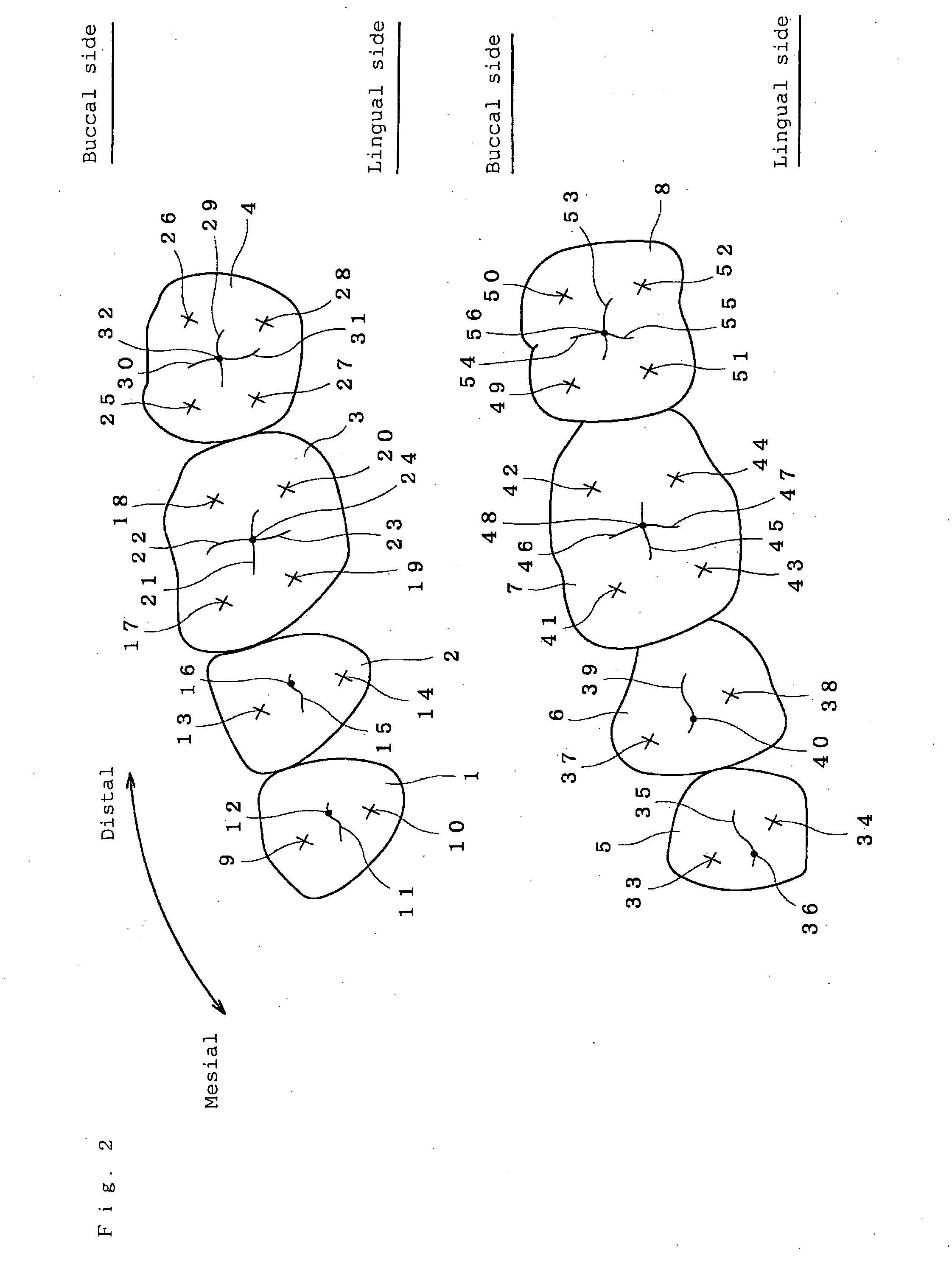
[0022]The invention is a technique for making artificial teeth as dental prosthetic appliances being dentures, and more particularly is a technique capable of applying for making of artificial molar teeth. The artificial molar teeth include a first molar tooth, a second molar tooth, a first premolar tooth, and a second premolar tooth, and in particular a combination of at least a pair of upper and lower opposed teeth is preferred, and more preferably a combination of four upper and lower artificial teeth including the first molar tooth, the second molar tooth, the first premolar tooth, and the second premolar tooth.

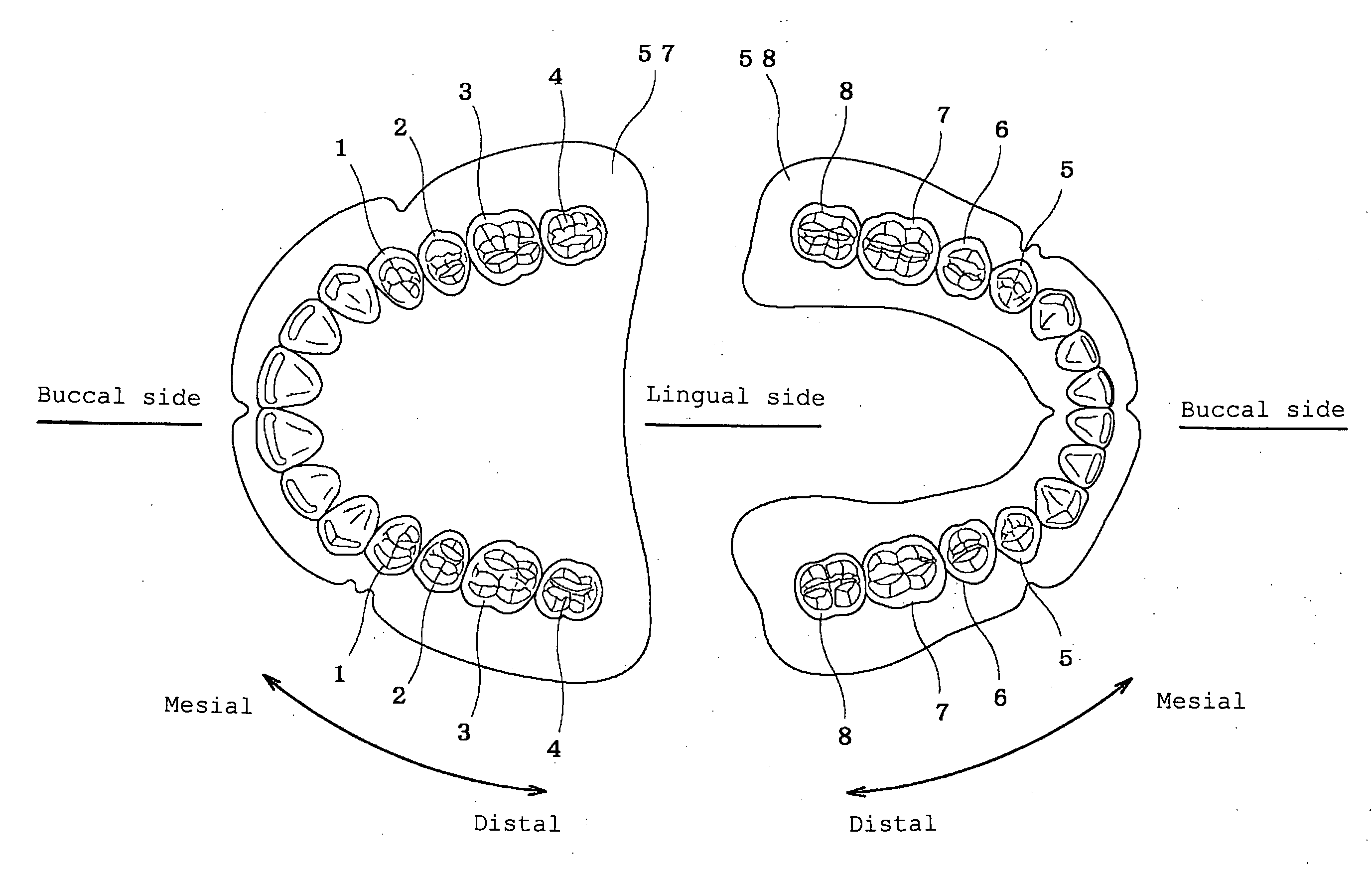
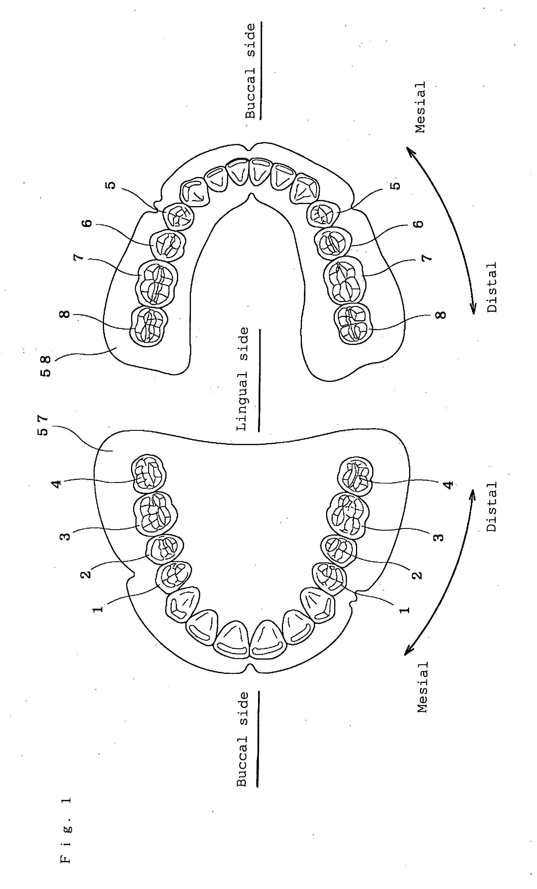
[0023]FIG. 1 shows an arrangement of all artificial teeth, showing an upper jaw at left and a lower jaw at right. In the artificial teeth, one tooth of the upper jaw corresponds to one tooth of the lower jaw. In the following description, a direction approaching to anterior ...


PUM


Abstract

The invention enables to arrange artificial molar teeth at appropriate positions according to the oral cavity environment of each patient without requiring advanced techniques or experiences. The invention relates to artificial molar teeth having maxillary molar teeth 1 to 4 and mandibular molar teeth 5 to 8 to be arranged so as to form a pair on denture bases 57, 58 to be mounted on upper and lower jaws in an oral cavity, in which one cusp out of the cusps of the maxillary molar teeth 1 to 4 and the mandibular molar teeth to 8 is engaged with a fossa of the antagonist, and at least one of the other cusps is engaged with a groove of the antagonist.

Description

BACKGROUND OF THE INVENTION[0001]The present invention relates to artificial molar teeth capable of easy arrangement when making a dental prosthetic appliance, and easy chewing at the time of mounting it as dentures.Background Art[0002]Arrangement of artificial molar teeth when making a dental prosthetic appliance demanded advanced techniques and experiences. It was particularly difficult to arrange opposed teeth in a proper position relation. In conventional artificial teeth, the relation of cusps and fossae of the teeth was considered to be important, and it was desired to make a stable shape so that each of a plurality of cusps is possible to engage with the fossae. Further, it was desired to develop artificial teeth which do not require much grinding after arrangement or large changing of the surface state.[0003]Patent document 1 below discloses artificial molar teeth in which a lingual cusp, a buccal cusp, and a fossa are formed on the occlusal surface of maxillary molar teeth,...

Claims


Application Information

Patent Timeline
IPC IPC(8): A61C13/10
CPCA61C13/097A61C13/1016A61C13/0027A61C13/10
Inventor KADOBAYASHI, YUSEI
Owner SHOFU INC
Learn More