
Control device, laser irradiation device, optimization font data database, recording method, and computer-readable storage medium

a technology of laser irradiation and control device, which is applied in the direction of recording apparatus, instruments, and thermography, can solve the problems of shortening the life of the medium, degrading the medium, and deteriorating the thermodynamic rewritable medium, so as to eliminate the influence of the rewritable or write-once medium

Active Publication Date: 2010-02-18
RICOH KK
View PDF1 Cites 34 Cited by
  • Summary
  • Abstract
  • Description
  • Claims
  • Application Information

AI Technical Summary

Benefits of technology

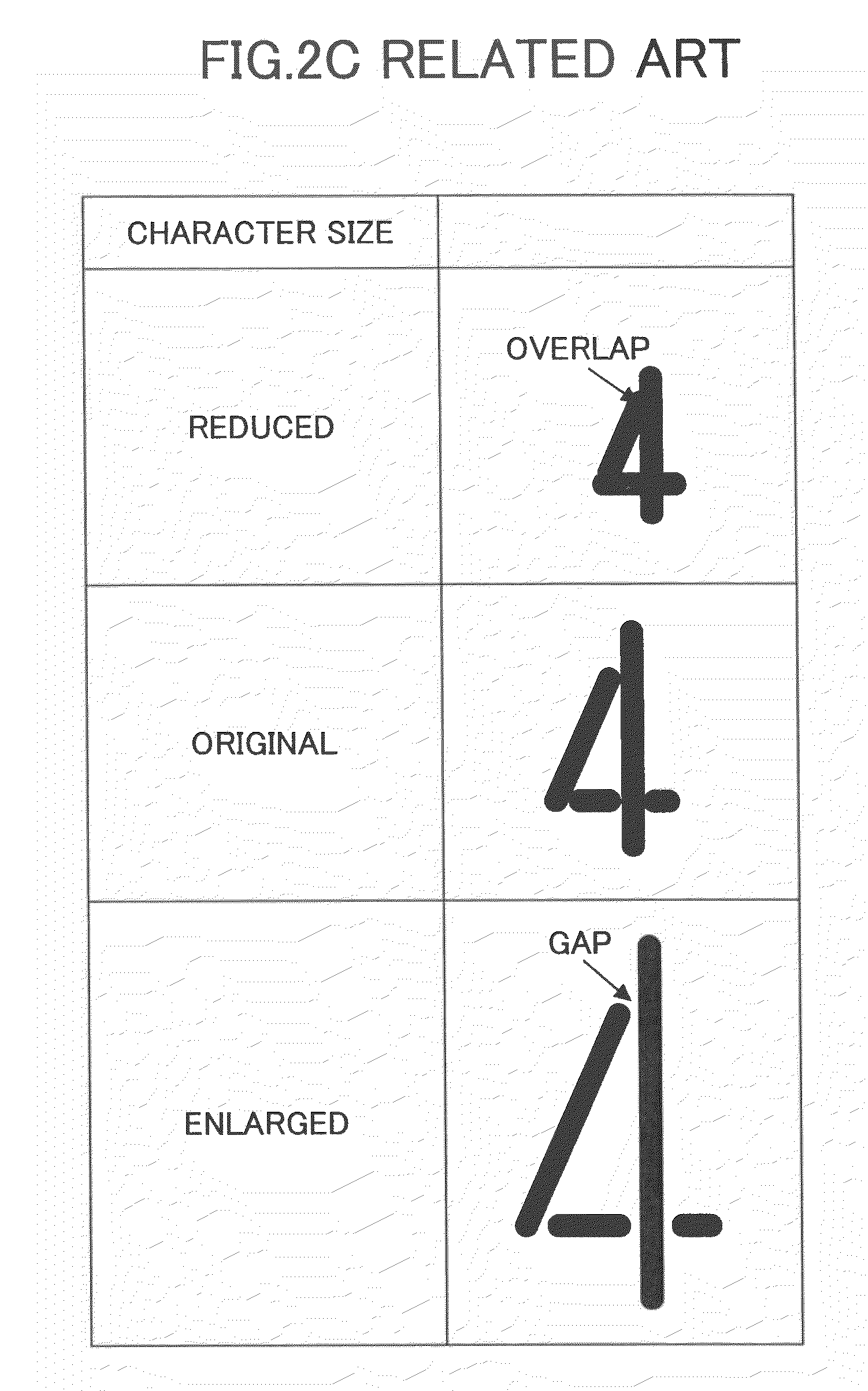
[0024]In one aspect of the invention, the present disclosure provides a control device for controlling a laser irradiation device, which is able to eliminate the influences on a rewritable or write-once medium by excessive heating of the medium by laser irradiation due to a gap or overlap between strokes, by taking into consideration the thickness of strokes and the size of characters.

Problems solved by technology

However, if excessive heating is applied, the thermal rewritable medium will be deteriorated, which will shorten the life of the medium or will degrade the medium so as to disable erasing of information completely.
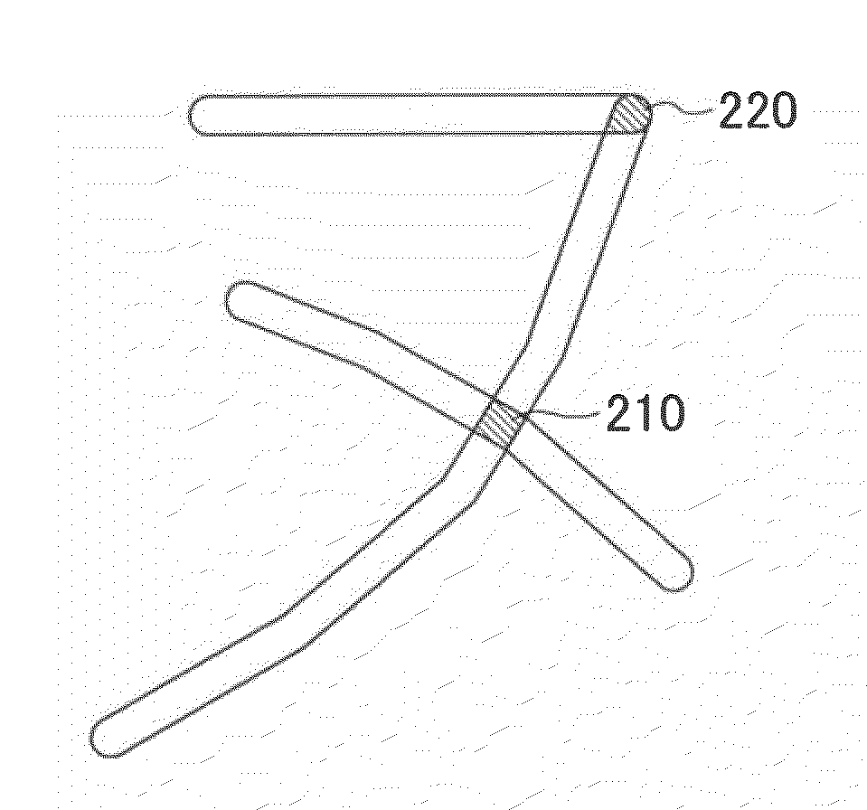
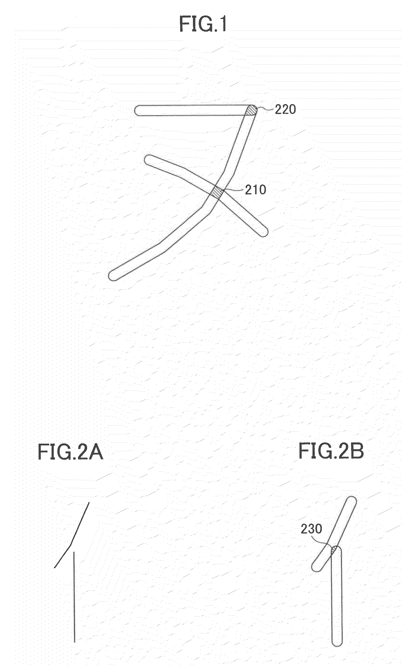
Because of the influence of the inertia of the mirror for controlling the irradiation direction of a laser beam, the laser irradiation is applied near the turn-back part 220 for a comparatively long time, and the thermal rewritable medium is heated excessively at the turn-back part 220, and the thermal rewritable medium may be damaged at this point.
However, there is no disclosure in Japanese Laid-Open Patent Publication No. 2006-306063, Japanese Patent No. 3990891, and Japanese Laid-Open Patent Publication No. 2008-179135 of how to detect an overlapping portion or a turn-back portion in a character being drawn.
As described above, a line segment drawn by laser irradiation has a certain width, and therefore it is difficult for the methods and devices according to Japanese Laid-Open Patent Publication No. 2006-306063, Japanese Laid-Open Patent Publication No. 2004-341373 and Japanese Laid-Open Patent Publication No. 2008-179135 to certainly prevent occurrence of a gap or overlap between strokes at a crossing point, a turn-back point or the like of a character being drawn, which is influenced by the size of characters and the thickness of strokes.

Method used


Image

  • Control device, laser irradiation device, optimization font data database, recording method, and computer-readable storage medium
  • Control device, laser irradiation device, optimization font data database, recording method, and computer-readable storage medium
  • Control device, laser irradiation device, optimization font data database, recording method, and computer-readable storage medium

Examples


embodiment 1

[0072]A description will be given of the invention. FIG. 4 illustrates the hardware composition of the laser irradiation device 200 of this embodiment.

[0073]As illustrated in FIG. 4, the laser irradiation device 200 of this embodiment includes a control device 100 which controls the whole laser irradiation device 200, and a laser irradiation part 160 which emits a laser beam. The laser irradiation part 160 includes a laser oscillator 11 which emits a laser beam, a direction control mirror 13 which changes a direction of radiation of the laser beam, a direction control motor 12 which drives the direction control mirror 13, an optical lens 14, and a focusing lens 15.

[0074]The laser oscillator 11 may be any of a semiconductor laser (e.g. LD (laser diode)), a gas laser, a solid state laser, a liquid laser, etc. The direction control motor 12 controls the direction of the reflection surface of the direction control mirror 13 with respect to the two axial directions. The direction control...

embodiment 2

[0251]FIG. 25A illustrates the functional composition of a device 170 which generates the optimization font data, and FIG. 25B illustrates the functional composition of the laser irradiation device 200 of the invention. In FIG. 25A and FIG. 25B, the elements which are the same as corresponding elements in FIG. 10 are designated by the same reference numerals, and a description thereof will be omitted.

[0252]The points different from FIG. 10 are that the device 170 in FIG. 25A includes an optimization font data generation unit 123 and an optimization font data database 121, and the laser irradiation device 200 in FIG. 25B includes an optimization font data acquiring unit 122. The device 170 which generates optimization font data uses a computer as well as the control device 100 as substance. As is apparent from FIG. 25A, the process to generate optimization font data is the same as that of the embodiment 1 in FIG. 10.

[0253]The optimization font data generation unit 123 generates the o...

embodiment 3

[0275]Next, a description will be given of embodiment 3 of the invention. In this embodiment, the configuration of endpoints of a line segment will be explained. FIGS. 28A-28C are diagrams for explaining coloring of the endpoints of a line segment.

[0276]FIG. 28A illustrates the relation between the center of a laser beam and the movement of the circle formed by the laser beam. FIG. 28B illustrates the relation between the locus of a laser beam and the temperature.

[0277]Even if the endpoint of a line segment has the slightly low temperature up sensitivity to the heat applied from the outside of rewritable medium 20 and applies heat by a laser beam, it may not immediately reach the coloring temperature. In this case, as illustrated in FIG. 28B, even if it is the area covered by the path of the laser beam, the area 410 near the endpoint of a line segment is not fully heated, and may not be colored.

[0278]In the case of FIG. 28A, a line segment being drawn in the horizontal direction is ...


PUM


Abstract

A control device controls a laser irradiation device to record visible information on a medium by irradiation of a laser beam. The control device includes a drawing information storage unit which stores drawing information of line segments contained in line images of characters, numbers, and symbols. A drawing information acquiring unit acquires drawing information of a line image as an object to be drawn. A thickness information acquiring unit acquires thickness information which specifies a thickness of each line segment. An overlapping line segment detecting unit detects a pair of line segments drawing ranges of which, inclusive of the line segment thickness, overlap each other, based on the thickness information and the drawing information. A line dividing / shortening unit divides or shortens at least one of the pair of line segments so that the drawing ranges of the pair of line segments do not overlap each other.

Description

BACKGROUND OF THE INVENTION[0001]1. Field of the Invention[0002]This invention relates to a control device which controls a laser irradiation device to record visible information, such as characters, on a medium by irradiation of a laser beam. More particularly, this invention relates to a laser irradiation device control device which is adapted to minimize damages of a recording surface of a rewritable or write-once medium after visible information, such as characters, is recorded on the medium by irradiation of a laser beam.[0003]2. Description of the Related Art[0004]In recent years, a laser irradiation device (or a laser marker) is marketed and this laser irradiation device employs the technology which records characters, numbers, symbols, etc. on a medium by irradiating the medium with a laser beam. By irradiation of a laser beam, the medium absorbs the laser beam and is thereby heated, so that visible information, including characters, numbers, and symbols, is recorded on the ...

Claims


Application Information

Patent Timeline
IPC IPC(8): G11B7/00
CPCG06K15/029G06K15/1835G06K15/1228B41J2/4753B41M5/24B41M5/26
Inventor HASEGAWA, FUMIHIROISHIMI, TOMOMI
Owner RICOH KK
Learn More