Apparatus and method for phase fronts based on superluminal polarization current

a phase front and superluminal technology, applied in the direction of electrical apparatus, individually energized antenna arrays, antennas, etc., can solve the problems of difficult for an aircraft imaged by such radiation to detect where this radiation comes, and it is almost impossible for electronics on the aircraft to synthesize a rogue reflection

Active Publication Date: 2010-02-18
TRIAD NAT SECURITY LLC +1
View PDF1 Cites 9 Cited by
  • Summary
  • Abstract
  • Description
  • Claims
  • Application Information

AI Technical Summary

Benefits of technology

[0013]The invention is a radiation source involving phase fronts emanating from an accelerated, oscillating, superluminal (that is, faster than light in vacuo) polarization current. The present invention using a superluminal source shows that the phase fronts from such a source can be made to be very complex. Consequently, it can be very difficult for an aircraft imaged by such radiation to detect where this radiation comes from. Moreover, the complexity of the phase fronts makes it almost impossible for electronics on an aircraft to synthesize a rogue reflection. A simple directional antenna and timing system should, on the other hand, be sufficient for the radar operators to locate the aircraft, given knowledge of their own source's speed and modulation pattern.
[0014]The superluminal source has another advantage; the radiation from the source may be steered electronically (that is, without moving the antenna) by changing the speed at which the distribution pattern of the polarization current propagates, which can be controlled by the voltage switching function of the elements. Indeed, the linearity of the emission process makes it possible for a superluminal source to emit tightly-beamed radiation of several different frequencies in several directions simultaneously.
[0015]Radar detection of aircraft (and indeed ships and other vehicles) is used by virtually all branches of the armed forces. The invention can limit the vulnerability of current radar systems.

Problems solved by technology

Consequently, it can be very difficult for an aircraft imaged by such radiation to detect where this radiation comes from.
Moreover, the complexity of the phase fronts makes it almost impossible for electronics on an aircraft to synthesize a rogue reflection.

Method used


Image

  • Apparatus and method for phase fronts based on superluminal polarization current
  • Apparatus and method for phase fronts based on superluminal polarization current
  • Apparatus and method for phase fronts based on superluminal polarization current

Examples


Embodiment Construction

[0035]According to the embodiment(s) of the present invention, various views are illustrated in FIGS. 1-10 and like reference numerals are being used consistently throughout to refer to like and corresponding parts of the invention for all various views and figures of the drawing. Also, please note that the first digit(s) of the reference number for a given item or part of the invention should correspond to the Fig. number in which the item or part is first identified.

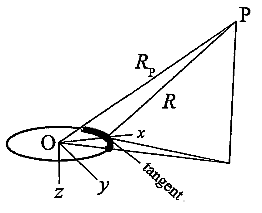
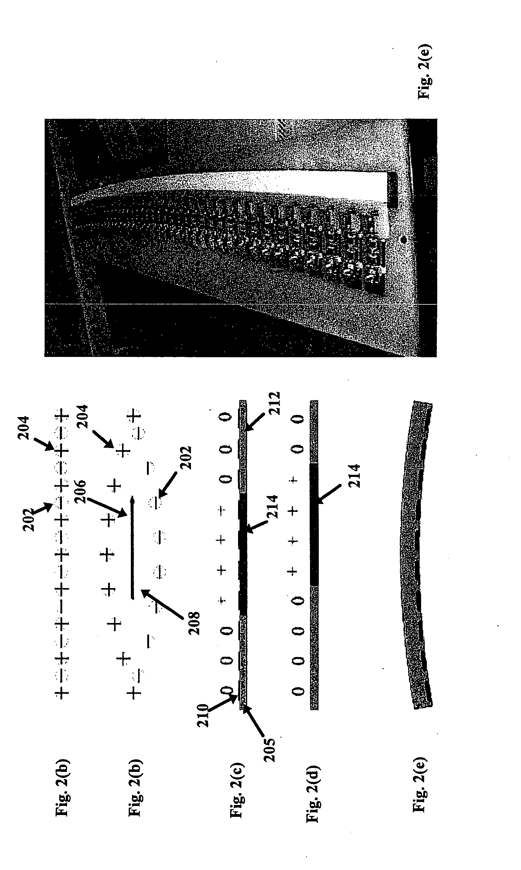
[0036]One embodiment of the present invention comprising an oscillating superluminal polarization current radiation source teaches a novel apparatus and method for emitting a complex phase front. The apparatus can include a dipole antenna array having elements excited in phase including a curved solid dielectric strip having negative and positive ions and having electrodes coupled above and a ground plate coupled below and said dielectric having a finite polarization region created by selectively applying a spatially v...


PUM


Abstract

An apparatus and method for a radiation source involving phase fronts emanating from an accelerated, oscillating polarization current whose distribution pattern moves superluminally (that is, faster than light in vacuo). Theoretical predictions and experimental measurements using an existing prototype superluminal source show that the phase fronts from such a source can be made to be very complex. Consequently, it will be very difficult for an aircraft imaged by such a radiation to detect where this radiation has come from. Moreover, the complexity of the phase fronts makes it almost impossible for electronics on an aircraft to synthesize a rogue reflection. A simple directional antenna and timing system should, on the other hand, be sufficient for the radar operators to locate the aircraft, given knowledge of their own source's speed and modulation pattern.

Description

1. STATEMENT REGARDING FEDERAL RIGHTS[0001]This invention was made with partial government support under Contract No. DE-AC52-06NA25396 awarded by the U.S. Department of Energy. The government has certain rights in the invention.2. BACKGROUND OF INVENTION[0002]This invention relates generally to radiation emitting sources for sensing targets and, more particularly, to radiation emitting sources, for example radar systems, which emit radiation and sensing reflections for target detection.[0003]In the past, there have been known methods employed for locating radar emitter sources, which required the knowledge of several parameters related to the operation of the emitter source measurements made from two or more known spatial locations, and / or the known rate of relative motion of the emitter source. Conventional radar sources can be vulnerable to countermeasures because the emitted radiation possesses rather simple phase fronts. The countermeasures that can be employed by an aircraft t...

Claims


Application Information

Patent Timeline
Patent Type & Authority Applications(United States)
IPC IPC(8): H01Q3/34
CPCH01Q3/34H01Q3/44H01Q21/22H01Q21/20H01Q21/061
Inventor SINGLETON, JOHNARDAVAN, HOUSHANGARDAVAN, ARZHANG
Owner TRIAD NAT SECURITY LLC
Why Eureka
Try Eureka