Two-stroke engine emission control

Inactive Publication Date: 2010-02-18
ZHEJIANG YAT ELECTRICAL APPLIANCE CO LTD
View PDF57 Cites 9 Cited by
  • Summary
  • Abstract
  • Description
  • Claims
  • Application Information

AI Technical Summary

Benefits of technology

[0007]The object of the present invention is to provide a stratified scavenging engine that introduces a predetermined efficient amount of airhead in the desired direction and with the proper timing.
[0009]The port configuration of the present invention provides for timely discharging a volume of air from both the primary and secondary scavenging ports and then followed by discharging the volume of air / mixture from the ports. During the operation of one embodiment of the present invention, the transfer passage closer to the exhaust port is pre-pressurized since it is always in fluid communication with the crankcase, while the secondary transfer system is fluidly connected to the crankcase only when the piston is in a first position (bottom dead center position) and is not fluidly connected to the crankcase i.e., blind, when the piston is in a second position (top dead center position). Both ports discharge the air head into the cylinder chamber, and because the primary port is pre-pressurized, it does it first, then the secondary port discharges. In both ports the air-fuel mixture follows the air.
[0011]It also must be noted that several manufacturers have tried to reach the ports adjacent to the exhaust port with external ducting from the air filter, or long channels through the piston skirt. These methods increase the width of the engine or increase the weight of the piston since the lower peripheral channels creates undercuts in the internal walls difficult to core out by traditional die cast systems. The design of the engine of the present invention is configured such that the air is transferred towards the primary scavenging passages adjacent to the exhaust port without using external ducting. Also the features are designed to allow easy manufacturing by die-casting.
[0013]One object of the present invention is to provide the appropriate timing for releasing the air head into the cylinder chamber, thus improving the engine efficiency while maintaining to a minimum the raw hydrocarbon losses.
[0015]Another object the present invention is to provide a two-cycle engine configured to provide adequate delivery of pure air into the cylinder chamber while maximizing the delivery of air / fuel mixture to increase the engine specific power and further reduce raw hydrocarbon losses.

Problems solved by technology

The delay on the air or fuel / air ejection from the transfer ports can be affected negatively by what is called blow-down gases.
This affects negatively the effect of port height and discharge timing is difficult to predict.

Method used


Image

  • Two-stroke engine emission control
  • Two-stroke engine emission control
  • Two-stroke engine emission control

Examples


Embodiment Construction

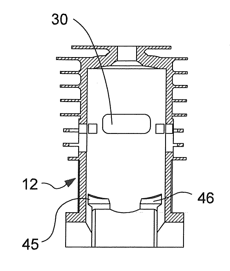
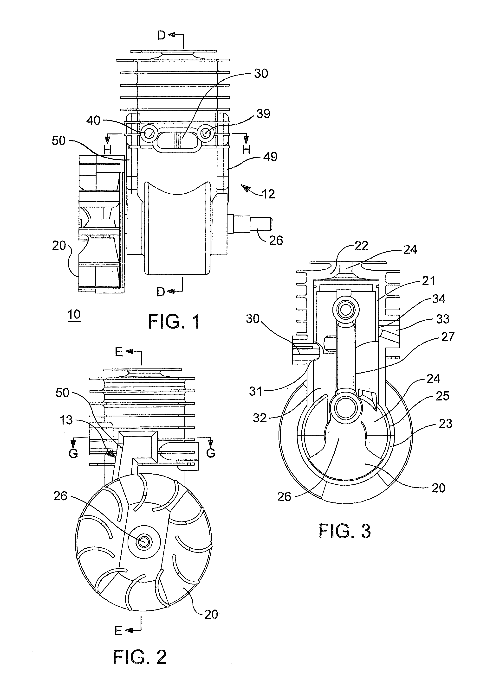
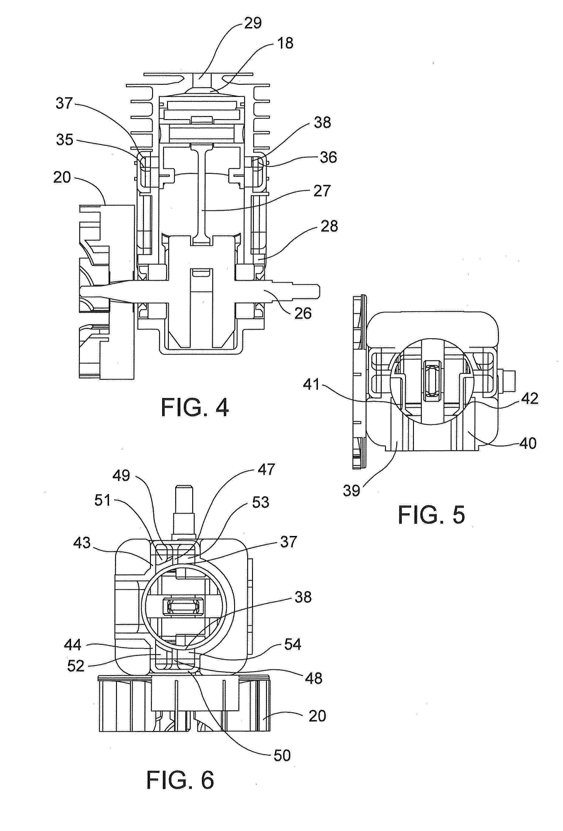
[0090]The present invention provides an engine that includes the basic elements found in traditional two-stroke engine as seen in the attached figures. According to a first embodiment, and specifically referring now to the engine assembly views as represented throughout the Figures and generally designated 10. A piston 21 is configured to move in a reciprocating motion within a cylinder 22, the cylinder 22 having a crankcase 25 and main bearing supports 28. Covering the bottom opening of the cylinder 22 is a crankcase cap 23. The crankcase cap 23 forms an internal chamber or crankcase 24 when joined with extended body 25 at the opened face of the cylinder 22. The piston 21 is attached to the crankshaft 26 by a connecting rod 27. Attached at one end of the crankshaft is the flywheel 20 having cooling fins and a set of magnets conventional within the art.

[0091]The crankcase 25 includes the crankshaft main bearing supports 28 that are shared with the crankcase cap as shown. The cylinde...


PUM


Abstract

A two-stroke internal combustion engine is provided. The engine includes a block defining a crankcase for enclosing a fuel mixture and a cylinder chamber formed at an end of a cylinder bore, an air passage in fluid communication with the cylinder bore, a scavenging transfer passage communicating between the crankcase and the cylinder chamber and having a primary transfer port in communication with a secondary transfer port, the secondary port having a first and a spaced-apart second window with a bridge spanning the space therebetween, and a piston slideably positioned in the cylinder bore and having a channel formed in a periphery of the piston and having a piston opening defined therein for providing selective communication between the crankcase and the transfer passage.

Description

CROSS-REFERENCE TO RELATED APPLICATIONS[0001]This application claims priority to U.S. Provisional Patent Application No. 61 / 088,024 which was filed on Aug. 12, 2008, the contents of which are hereby incorporated.BACKGROUND OF THE INVENTION[0002]The typical design of two-cycle engines uses a stream of new air / fuel mixture to finish evacuating the burned gases left in the cylinder chamber from the previous combustion cycle. The exhaust port remains open during the time while the scavenging ports that are in communication with the crankcase are open. This causes some of the scavenging gases (air-fuel mixture) to escape through the exhaust port. These un-burned gases then escape to the atmosphere creating pollution and reducing fuel efficiency.[0003]Many improvements have been made throughout time to improve the filling of the cylinder chamber with fresh mixture and to avoid losses of fuel. Some of these improvements include special geometry of the transfer passages configured to direct...

Claims


Application Information

Patent Timeline
IPC IPC(8): F02F1/22F02B75/06
CPCF02F1/22
Inventor LAYDERA-COLLINS, IMACK
Owner ZHEJIANG YAT ELECTRICAL APPLIANCE CO LTD
Why Eureka
Try Eureka