
Array type pressure sensing apparatus and pressure measurement method using the same

Active Publication Date: 2010-02-18
IND TECH RES INST
View PDF8 Cites 61 Cited by
  • Summary
  • Abstract
  • Description
  • Claims
  • Application Information

AI Technical Summary

Benefits of technology

[0018]The present invention provides an array type pressure sensing apparatus suitable for multi-touch sensing and pressure quantification for gray scale identification. The array type pressure sensing apparatus and standard resistors are manufactured by micro electro mechanical system (MEMS) processing, complementary metal oxide semiconductor (CMOS) processing or printing without additional manufacturing cost.
[0020]In one embodiment, the present invention provides an array type pressure sensing apparatus suitable for multi-touch sensing and pressure quantification for gray scale identification. The array type pressure sensing apparatus comprises a plurality of first axes, a plurality of second axes, a plurality of piezoresistive units, a third axis, a plurality of standard resistors and a control unit. The second axes are disposed crisscross with the first axes, and there is one piezoresistive unit disposed on the cross between one first axis and one second axis. The piezoresistive unit is capable of exhibiting different resistance values when being applied with different pressures. The third axis is disposed crisscross with the first axes, and there is one standard resistor on the cross between one first axis and the third axis. The standard resistor is capable of exhibiting a constant resistance value (with resistance error less than 1%) when being applied with different pressures. The control unit has a plurality of I / O ports respectively coupled to the first axes, the second axes and the third axis, through which the control unit performs a tri-state logic scanning and driving process on the first axes, the second axes and the third axis. Therefore, the array type pressure sensing apparatus exhibits at least the following advantages:

Problems solved by technology
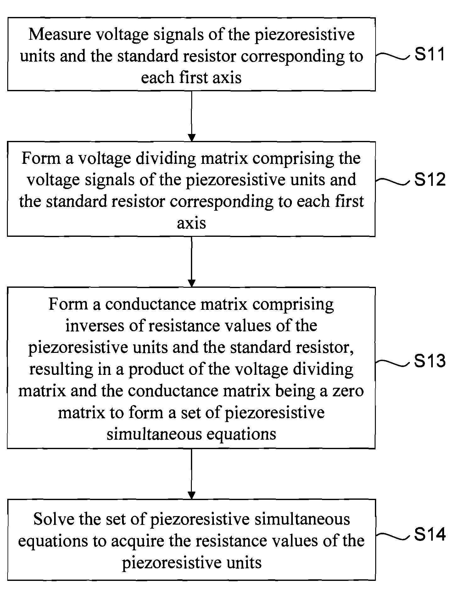
If large-area sensing is required, the number of pressure sensing units has to be increased, which leads to high hardware cost and difficulty in manufacturing sensing devices on a large area.
However, the scanning and driving architecture is easily affected by the leakage current due to minimal capacitive charge storage to cause error sensing and error identification in scanning and driving of the array type capacitive sensing device.
Moreover, an additional correction circuit is required to correct the pressure corresponding to capacitance variation because of low precision in electric signals corresponding to pressure by the charge amplification sensing architecture.
However, in this method, the driving method for the sensing circuit and its algorithm are too complicated, further leading to delay in calculation of pressure variations.
However, resistive multi-touch positioning and multi-touch pressure gray scale identification cannot be realized by the above constant current driving and scanning or constant voltage driving and scanning based on the x-axis and y-axis.
However, when resistive units 130 are applied with a pressure, resistance value variation due to the applied pressure causes resistance unbalance.
However, such a method can only be used to sense the position where the pressure is applied on the sensor but fails to precisely provide the pressure values through a pressure distribution of the resistive touch panel.
To further acquire the pressure distribution corresponding to precise pressure values, the resolution of the analog-to-digital converter in the micro-controller has to be improved, leading to complicated encoding operation and difficulty in realization of large-area, multi-linear scanning and driving nor high gray-scale pressure identification.
Furthermore, the sensitivity of the resistive touch devices cannot be improved.

Method used


Image

  • Array type pressure sensing apparatus and pressure measurement method using the same
  • Array type pressure sensing apparatus and pressure measurement method using the same
  • Array type pressure sensing apparatus and pressure measurement method using the same

Examples


Embodiment Construction

[0036]The present invention can be exemplified but not limited by the embodiments as described hereinafter.

[0037]FIG. 2 is a schematic diagram of an array type pressure identification system according to one embodiment of the present invention. To make it brief, FIG. 2 shows a circuit diagram of 3-wire multi-touch device. Referring to FIG. 2, the array type pressure sensing apparatus 200 of the present invention comprises a plurality of first axes 210 (210a, 210b, 210c), a plurality of second axes 220 (220a, 220b), a plurality of piezoresistive units 230, a third axis 240, a plurality of standard resistors 250 and a control unit 260. The first axes 210 can be exemplified by a plurality of row metal wires (like the conventional x-axes). The second axes 220 can be exemplified by a plurality of column metal wires (like the conventional y-axes). The first axes 210 and the second axes 220 disposed perpendicularly crisscross. However, the present invention is not limited to the above arra...


PUM


Abstract

An array type pressure sensing apparatus suitable for multi-touch sensing and pressure quantification for gray scale identification is provided. The array type pressure sensing apparatus includes a plurality of first axes, a plurality of second axes, a plurality of piezoresistive units, a third axis, a plurality of standard resistors and a control unit. The second axes are disposed crisscross with the first axes, and there is one piezoresistive unit disposed on the cross between one first axis and one second axis. The third axis is disposed crisscross with the first axes, and there is one standard resistor on the cross between one first axis and the third axis. A pressure measurement method implemented using the array type pressure apparatus is also provided. The pressure measurement method is a gray scale identification method by pressure quantification of a linear piezo-resistive system.

Description

CROSS-REFERENCE TO RELATED APPLICATIONS[0001]This application claims priority under 35 U.S.C. §119(a) to Patent Application No. 097130787 filed in Taiwan on Aug. 13, 2008, the entire contents of which are hereby incorporated by reference.BACKGROUND OF THE INVENTION[0002]1. Field of the Invention[0003]The present invention generally relates to a pressure sensing apparatus and a pressure measurement method using the same and, more particularly, to an array type pressure sensing apparatus and a pressure measurement method using the array type pressure sensing apparatus.[0004]2. Description of the Prior Art[0005]With the development in technology, the pressure sensing apparatus has been widely used in the daily lives. For example, Tekscan has used gray-scale pressure sensing in home care identification and mat pressure sensing. Quantization of touch reception for biomimetic electronic skin has been provided. The resistive touch panel has been commercialized. In consumer electronics, mul...

Claims


Application Information

Patent Timeline
IPC IPC(8): G01L1/18
CPCG01L1/205G06F3/047G06F3/045G06F3/0414
Inventor YEH, SHAO-HSINGSHEN, YU-TANG
Owner IND TECH RES INST
Learn More