
Automated discovery of a topology of a distributed computing environment

Active Publication Date: 2010-02-04
IBM CORP
View PDF71 Cites 57 Cited by
  • Summary
  • Abstract
  • Description
  • Claims
  • Application Information

AI Technical Summary

Benefits of technology

[0009]The current topology may be discovered using environment-specific handlers. The environment-specific handlers may further convert the one or more discovered resources t

Problems solved by technology

However, the development environment from which a new application is developed is often different from an operations environment, e.g., a data center, which deploys the developed application.
In this regard, architects within the operations environment are typically burdened with the responsibility of carrying the developed application into operations.
However, information regarding existing resources in which the software solution may be deployed may not be readily available.
This can result in difficulty for successful deployment of the application within the operations environment, especially when that entity is forced to deal with solving configuration problems that arise from incompatibilities in the requirements of the developed application and the capabilities provided by the target operations environment.

Method used


Image

  • Automated discovery of a topology of a distributed computing environment
  • Automated discovery of a topology of a distributed computing environment
  • Automated discovery of a topology of a distributed computing environment

Examples


example extension

[0065

[0066]In one embodiment of the invention, the following example extension allows existing resource(s) to be found within Eclipse workspace configurations, and linkages to the resources to be created in a deployment topology:

      class=“com.ibm.ccl.soa.deploy.ide.internal.discoverer.-    IdeTopologyDiscoverer”    description=“%extension.ideTopologyDiscoverer.description”name=“%extension.ideTopologyDiscoverer” / >

example interface

[0067

[0068]In one embodiment of the invention, the following interface is implemented by the environment specific handler to discover the deployment topology:[0069]package com.ibm.ccl.soa.deploy.core;

import java.util.List; / *** Provides the interface for client extensions to provide a discoverer for* topology artifacts. Clients who extend* com.ibm.ccl.soa.deploy.core.topology / discoverer must* extend this class.* @since 1.0** / public abstract class TopologyDiscoverer { / *** This implementation of this method should specify whether the* discovery provider is capable of serving the request based on the* contents set in the filter.* @param filter*  the input filter instance that has the filter criteria.* @return true, if the provider can fulfill the criteria.** / public abstract boolean canDiscover(DiscoveryFilter filter); / *** The implementation of this method should return a list of the unit* decriptors based on the discovery criteria.** @param filter*  the input filter instance that has th...

example filter

[0070

[0071]In one embodiment of the invention, the following filter is used to define the search scope and the result for the deployment topology:[0072]package com.ibm.ccl.soa.deploy.core;

[0073]Referring to FIG. 6, a block diagram of a data processing system is depicted in accordance with the present invention. A data processing system 400, such as may be utilized to implement embodiments of the present invention, may comprise a symmetric multiprocessor (SMP) system or other configuration including a plurality of processors 402 connected to system bus 404. Alternatively, a single processor 402 may be employed. Also connected to system bus 404 is memory controller / cache 406, which provides an interface to local memory 408. An I / O bridge 410 is connected to the system bus 404 and provides an interface to an I / O bus 412. The I / O bus may be utilized to support one or more busses and corresponding devices 414, such as bus bridges, input output devices (I / O devices), storage, network adap...


PUM


Abstract

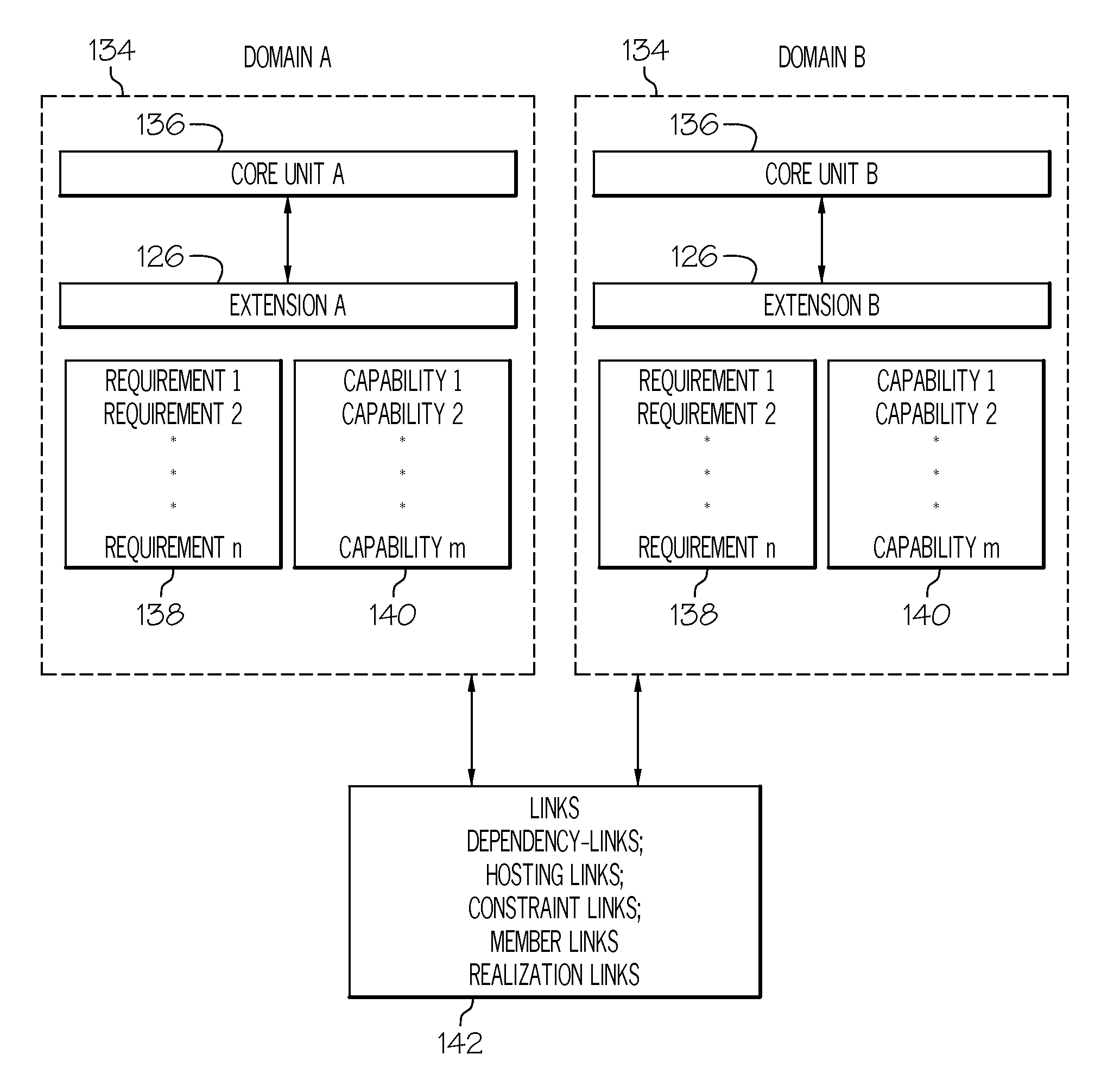
This invention provides an extensible means of defining the mechanism to find one or more type(s) or instance(s) of existing resources (files, databases, repositories, etc.) and automating their linkages to the artifacts to be created, based on the customizable matching rules.

Description

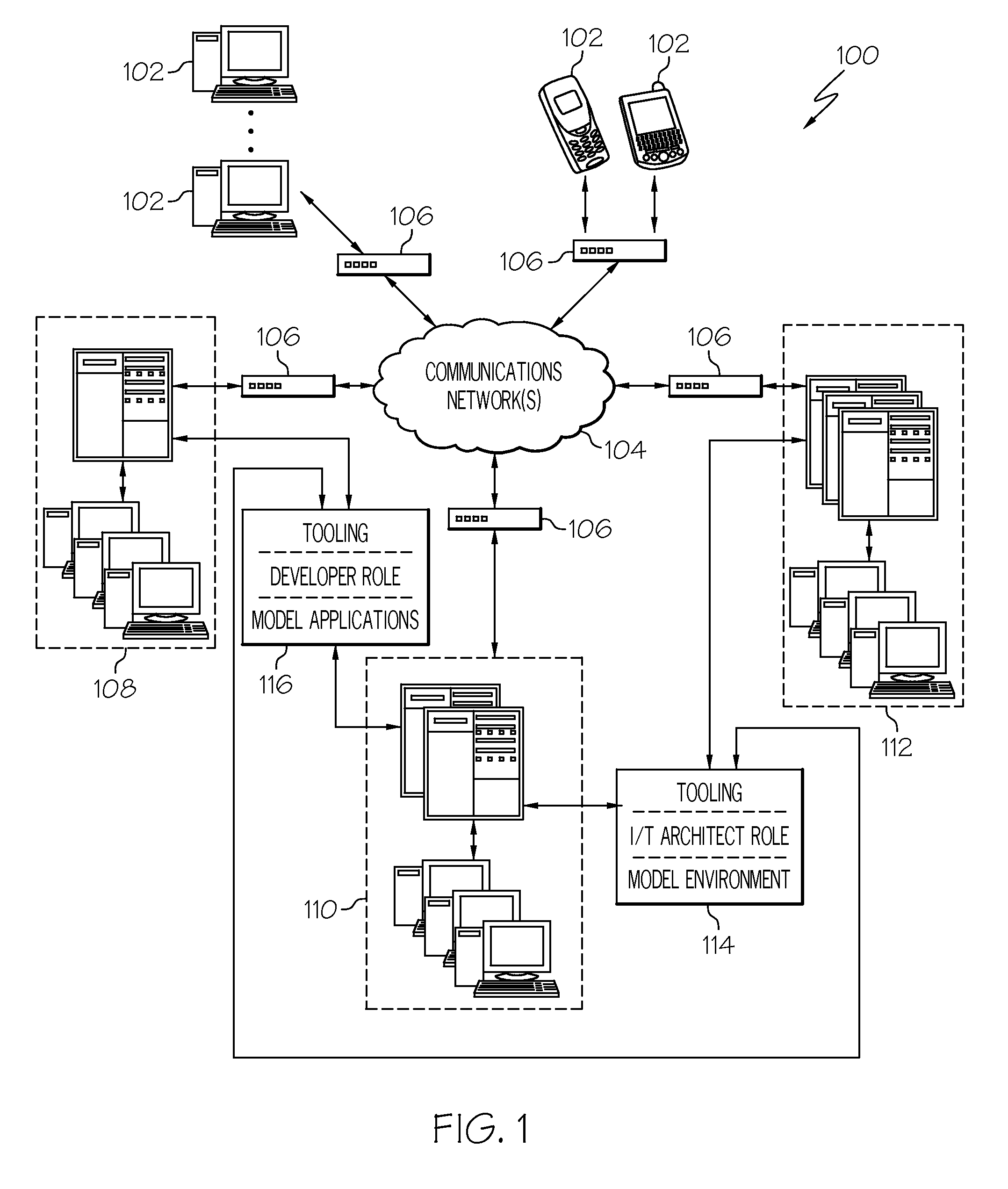
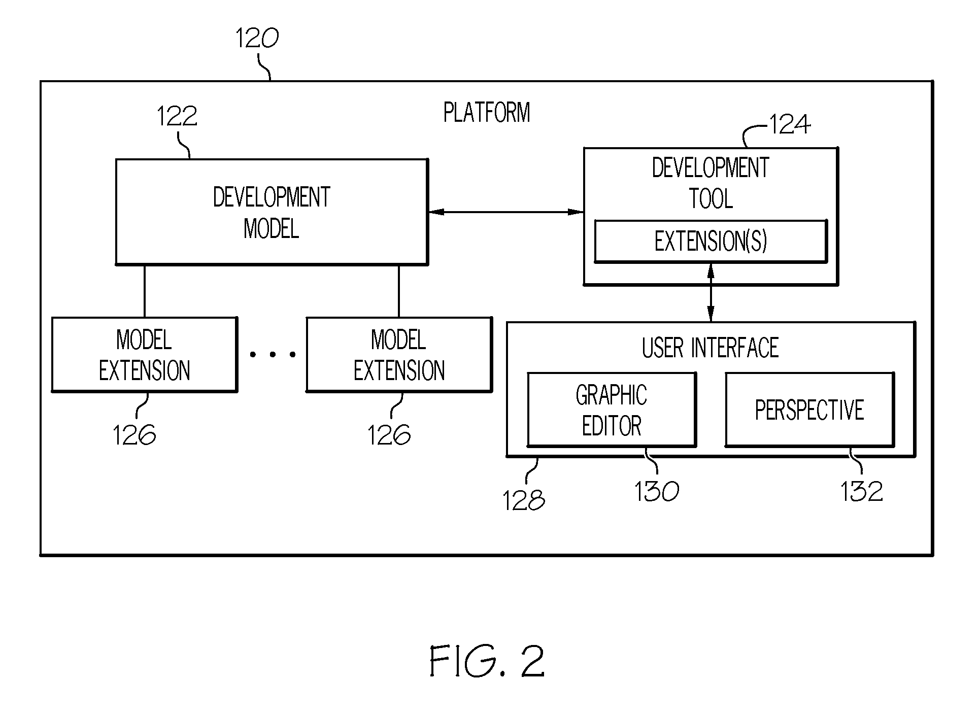
CROSS-REFERENCE TO RELATED APPLICATIONS[0001]This application is a continuation-in-part of U.S. application Ser. No. 12 / 181,737, filed Jul. 29, 2008, which is incorporated by reference herein in its entirety.BACKGROUND[0002]The present invention relates to distributed computing environments, and more particularly to developing and deploying software code in a distributed computing environment.[0003]In a typical application development environment, a software architect creates software applications, e.g., using conventional development tools. However, the development environment from which a new application is developed is often different from an operations environment, e.g., a data center, which deploys the developed application. In this regard, architects within the operations environment are typically burdened with the responsibility of carrying the developed application into operations.[0004]Development and deployment of a software solution often requires operation on existing re...

Claims


Application Information

Patent Timeline
IPC IPC(8): G06F15/173
CPCG06F9/5061
Inventor BERG, DANIEL CHRISTOPHERBLANCETT, BRAD LEEELDER, MICHAEL DAMEINHOLLIDAY, CHADKALANTAR, MICHAEL HUSAYNKONSTANTINOU, ALEXANDER V.MAKIN, NARINDERPOUYER, TIMOTHY ALLENSWANKE, JOHN E.
Owner IBM CORP
Learn More