
Ignition coil, in particular for an internal combustion engine of a motor vehicle

a technology of ignition coil and internal combustion engine, which is applied in the direction of transformer/inductance details, basic electric elements, inductance, etc., can solve the problems of reduced cross-section surface of magnet core (compared to rectangular cross-section), insufficient utilization of magnetic properties of sheet metal packets, and insufficient utilization of cross-section surface. , to achieve the effect of optimal utilization of cross-section surface, good magnetic properties of inner magnet core, and improved and uniform impregnation

Active Publication Date: 2010-02-04
ROBERT BOSCH GMBH
View PDF11 Cites 3 Cited by
  • Summary
  • Abstract
  • Description
  • Claims
  • Application Information

AI Technical Summary

Benefits of technology

[0005]Furthermore, it is described in DE 299 01 095 to provide an inner magnet core in a rod ignition coil which has a substantially rectangular cross section. Only the lowermost and the uppermost strips of the sheet-metal packet each have a reduced width, the width being approximately one third to one half of the width of the remaining sheet-metal strips. This makes it possible, according to DE 299 01 095, to achieve a cross section adapted to a circular cross section. The disadvantage is that the cross-section surface of the magnet core (compared to a rectangular cross section) is reduced and the magnetic properties of the sheet-metal packet are not optimally utilized. Moreover, the problems in the corner areas of the magnet core having the increased wire pull-off speeds and the associated disadvantageous effects during winding of the primary bobbin and the secondary bobbin remain.
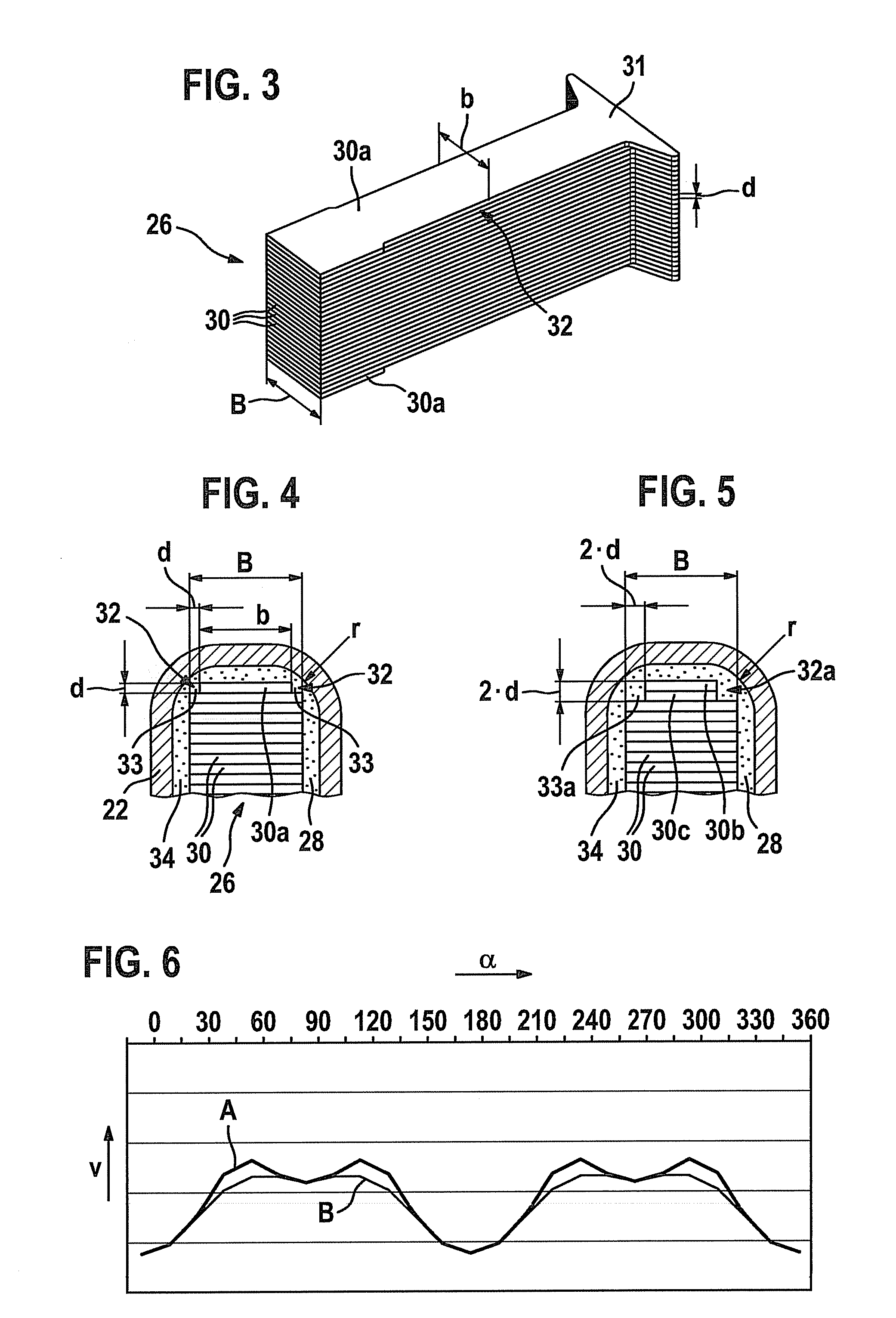
[0006]The ignition coil, in particular for an internal combustion engine of a motor vehicle according to example embodiments of the present invention, has the advantage that, with maximum utilization of the available cross-section surface within the primary and the secondary coils and thus good magnetic properties of the inner magnet core, the local speed peaks at the primary and the secondary bobbins during winding with the appropriate wire in the corner areas are reduced. This makes less tight winding of the primary bobbin and the secondary bobbin with the primary wire and the secondary wire possible, which results in a better and more uniform impregnation and thus a better insulation of the ignition coil.
[0007]Exemplary embodiments of the present invention are illustrated in the drawings and explained in greater detail in the following.

Problems solved by technology

This causes a compaction of the wire layers in the corner areas of the bobbins, which makes the subsequent impregnation or insulation of the primary coil and the secondary coil with the insulation resin more difficult, since the resin is unable to properly fill the spaces between the individual wire layers.
The disadvantage is that the cross-section surface of the magnet core (compared to a rectangular cross section) is reduced and the magnetic properties of the sheet-metal packet are not optimally utilized.
Moreover, the problems in the corner areas of the magnet core having the increased wire pull-off speeds and the associated disadvantageous effects during winding of the primary bobbin and the secondary bobbin remain.

Method used


Image

  • Ignition coil, in particular for an internal combustion engine of a motor vehicle
  • Ignition coil, in particular for an internal combustion engine of a motor vehicle
  • Ignition coil, in particular for an internal combustion engine of a motor vehicle

Examples


Embodiment Construction

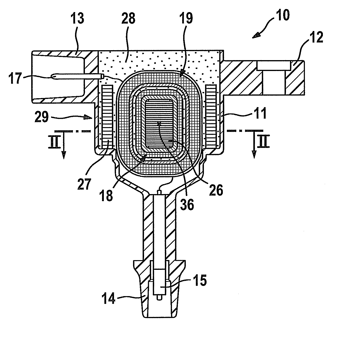
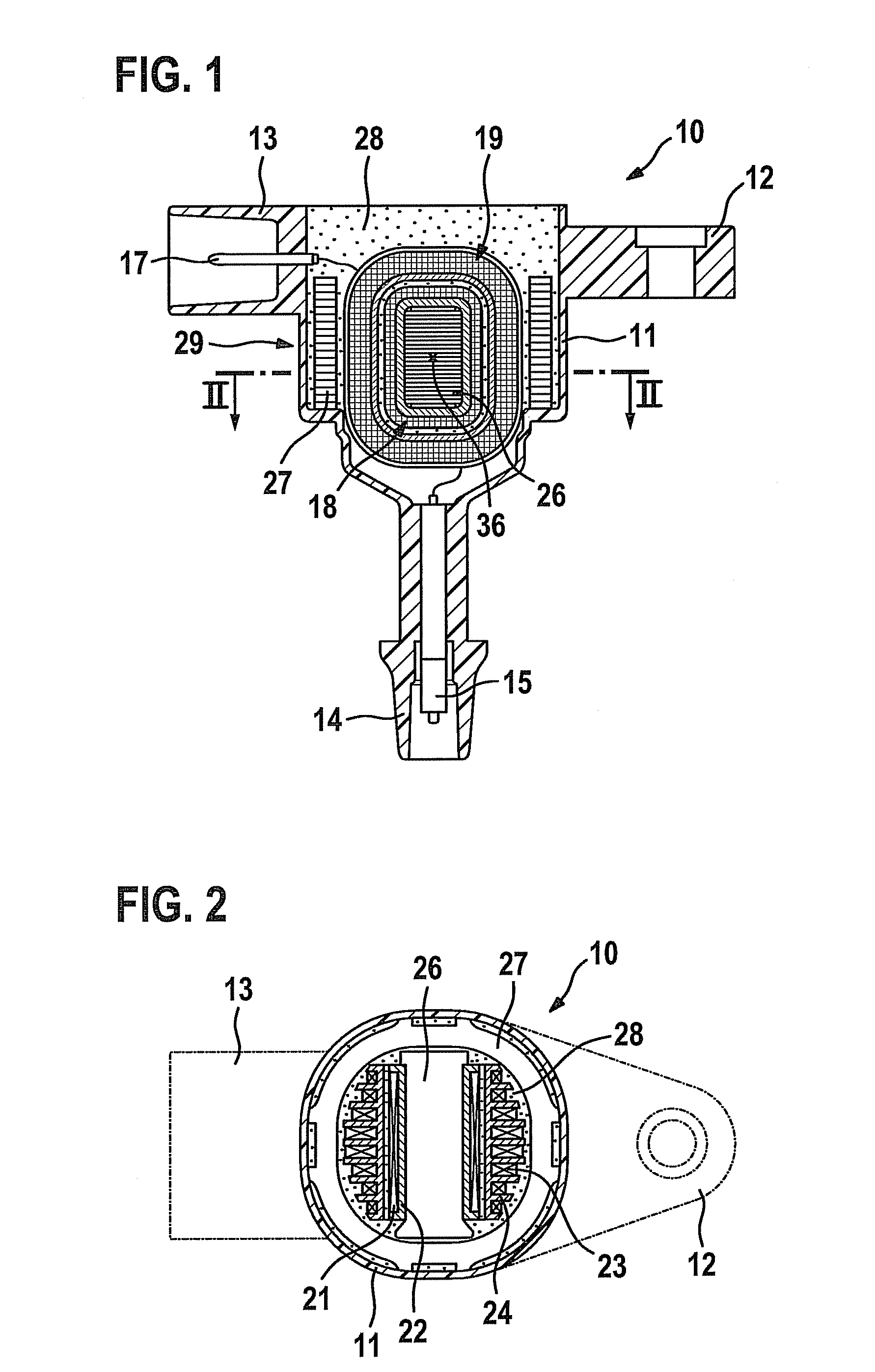
[0013]Ignition coil 10 shown in FIG. 1 is designed as a so-called compact ignition coil and is used for providing the ignition voltage for a spark plug of an internal combustion engine in a motor vehicle. Ignition coil 10 has a plastic housing 11 which is connectable, for example, to the cylinder head of the internal combustion engine via a connecting flange 12 molded onto housing 11. Opposite connecting flange 12, a connector 13 is molded for contacting ignition coil 10 with the on-board voltage of the motor vehicle. In the lower area, housing 11 also has a connecting piece 14 having an integrated high-voltage pin 15 which is contactable to the spark plug of the internal combustion engine which supplies the ignition power for igniting the mixture in the cylinder head. While contact 17 in connector 13 is electrically connected to a primary coil 18, high-voltage pin 15 is electrically coupled to a secondary coil 19. Primary coil 18 has a primary winding 21 which is wound on a primary...


PUM


Abstract

An ignition coil, in particular for an internal combustion engine of a motor vehicle, has an inner magnet core which is concentrically enclosed by a primary coil and a secondary coil. The inner magnet coil is made up of sheet-metal strips stacked on top of each other, the sheet-metal strips forming a substantially rectangular or square cross-section surface of the inner magnet core. At least the lower and the upper sheet-metal strips, delimiting the inner magnet core, have, at least in partial areas, a reduced width viewed in the longitudinal direction compared to the other sheet-metal strips of the inner magnet core. This makes a primary bobbin and a secondary bobbin having an enlarged corner radius and a more uniform winding density of the primary coil and the secondary coil possible.

Description

FIELD OF THE INVENTION[0001]The present invention relates to an ignition coil, in particular for an internal combustion engine of a motor vehicle.BACKGROUND INFORMATION[0002]Such an ignition coil is described in DE 100 14 115. The conventional ignition coil has an inner magnet core made up of lamellar sheet-metal strips which are stacked on top of each other. The sheet-metal strips form an overall rectangular cross-section surface. The inner magnet core is concentrically surrounded by a primary bobbin and a secondary bobbin. The shape of both the primary bobbin and the secondary bobbin is adapted to the cross-section shape of the inner magnet core, the primary bobbin and the secondary bobbin each having rounded edges along the corner areas of the inner magnet core. In addition, the spaces between the inner magnet core, the primary coil with its primary bobbin, and the secondary coil with its secondary bobbin are surrounded by an insulation compound, in particular by an insulation re...

Claims


Application Information

Patent Timeline
IPC IPC(8): H01F27/00
CPCH01F27/022H01F27/245H01F2038/122H01F38/12H01F27/306
Inventor STEINBERGER, WERNER
Owner ROBERT BOSCH GMBH
Learn More