
Driver amplifier having a programmable output impedance adjustment circuit

a technology of output impedance adjustment and driver amplifier, which is applied in the field of amplifiers and impedance matching, can solve the problems of amplifier distortion, the output impedance of the driver amplifier changes, and the power of the driver amplifier is decreased, so as to reduce the amount of capacitance, reduce the die area, and improve the effect of impedance matching

Active Publication Date: 2010-02-04
QUALCOMM INC
View PDF10 Cites 38 Cited by
  • Summary
  • Abstract
  • Description
  • Claims
  • Application Information

AI Technical Summary

Benefits of technology

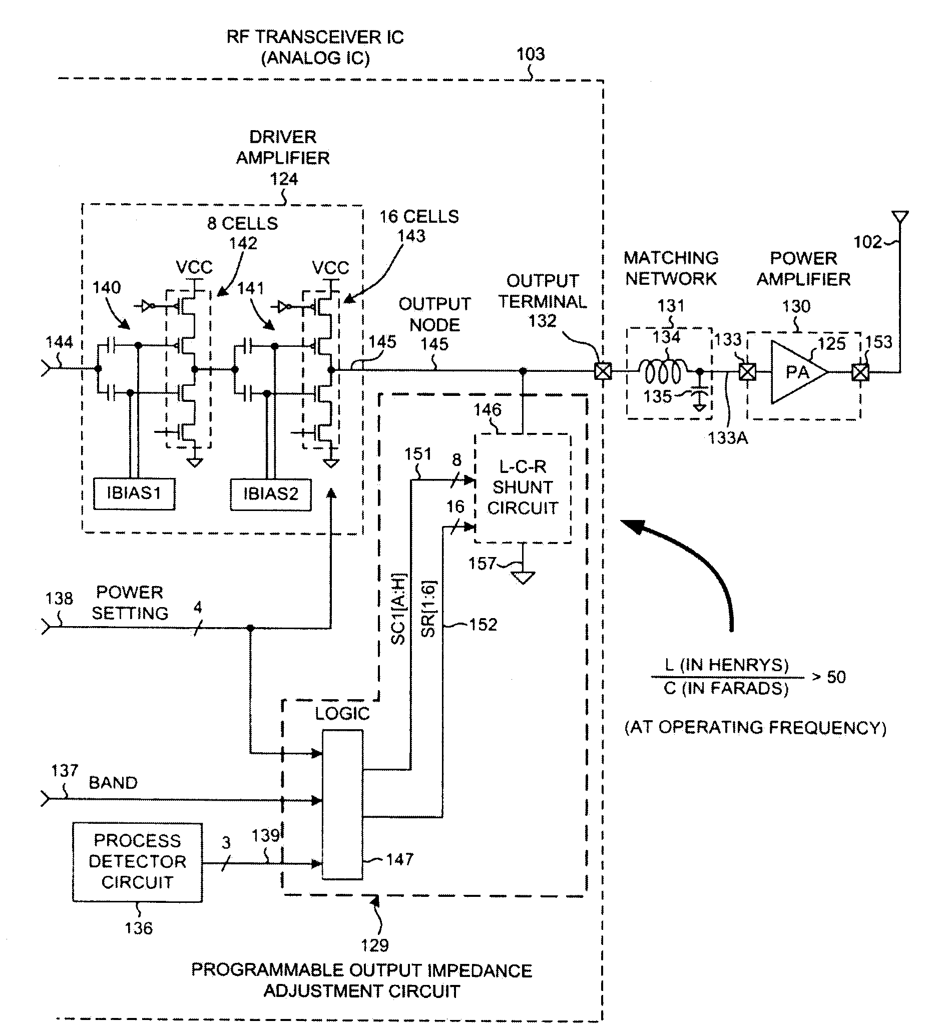
[0012]A novel Programmable Output Impedance Adjustment Circuit (POIAC) is provided within the first integrated circuit. The POIAC is coupled to the output node and affects the output impedance looking into the output terminal of the first integrated circuit. When the output impedance looking into the output terminal would otherwise have changed (for example, due to a driver amplifier power gain change), the POIAC adjusts how it loads the output node such that the overall output impedance looking into the output terminal remains substantially constant and such that good impedance matching at the input of the power amplifier is maintained. The POIAC involves an L-C-R shunt circuit involving a series-connected inductor and capacitance, thereby reducing the amount of capacitance required to perform the impedance matching function and thereby reducing die area. The POIAC performs its impedance matching function in multiple different communication frequency bands at least in part by changing the effective capacitance of the L-C-R shunt circuit.

Problems solved by technology

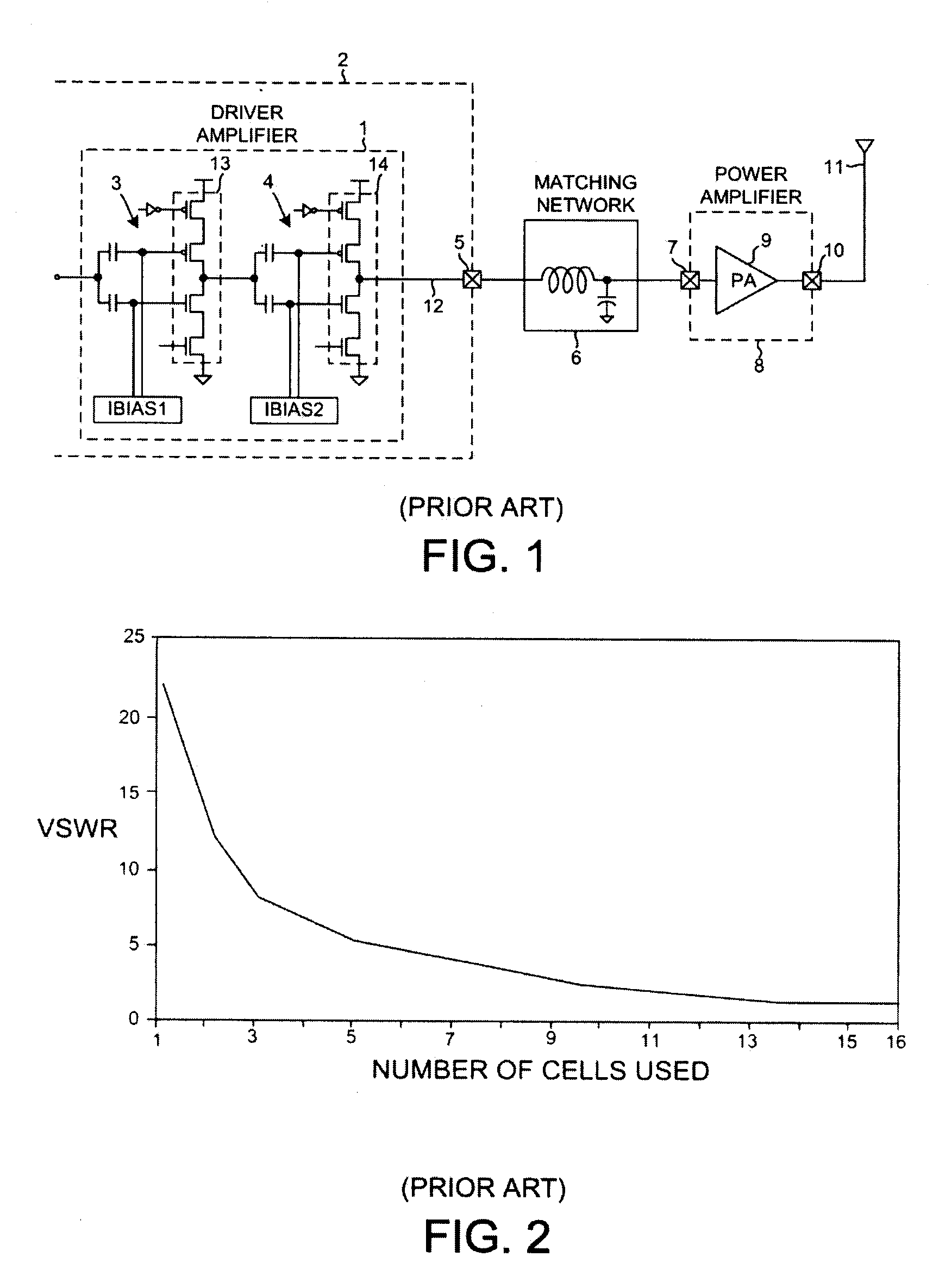
Unfortunately, as the power of the driver amplifier is decreased due to using fewer and fewer cells in the driver amplifier, the output impedance of the driver amplifier changes.
Regardless of whether the output impedance increases or decreases, the change in output impedance may lead to an undesirable impedance mismatch at terminal 7, and hence may lead to distortion in the amplifier.
This is undesirable and may result in undesirable distortion being introduced into the signal output onto antenna 11.
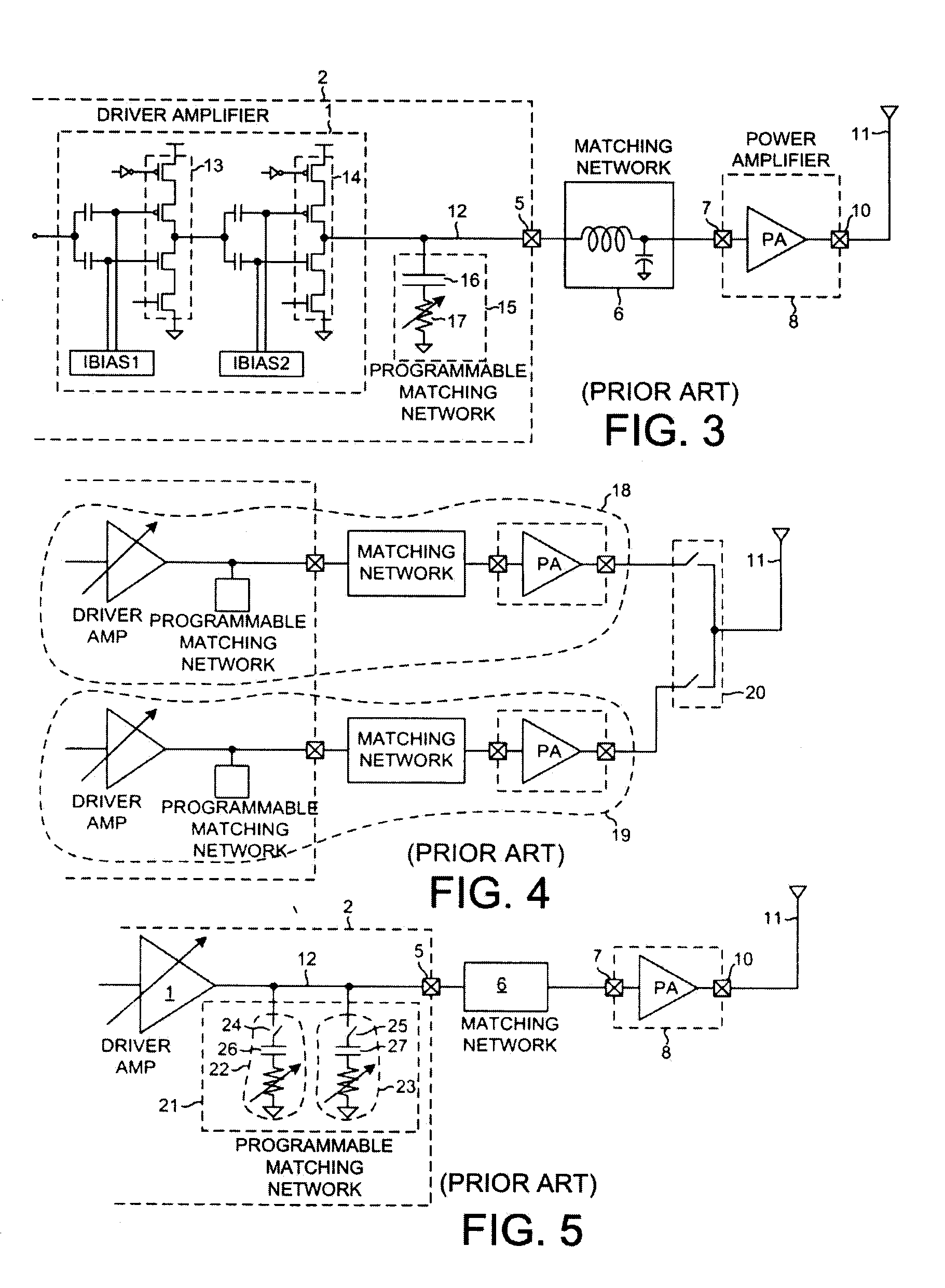
Unfortunately, the circuit of FIG. 3 may only be suitable for operation for signals in a single frequency band.
The circuit of FIG. 4 is, however, undesirably large and expensive in that two separate sets of driver amplifiers and matching networks and power amplifiers are used.
A considerable amount of die space may be consumed realizing these capacitors.

Method used


Image

  • Driver amplifier having a programmable output impedance adjustment circuit
  • Driver amplifier having a programmable output impedance adjustment circuit
  • Driver amplifier having a programmable output impedance adjustment circuit

Examples


Embodiment Construction

[0029]FIG. 6 is a very simplified high level block diagram of one particular type of mobile communication device 100 in accordance with one novel aspect. In this particular example, mobile communication device 100 is a 3G cellular telephone capable of operating in accordance with either a Code Division Multiple Access (CDMA) cellular telephone communication protocol or a GSM (Global System for Mobile Communications) cellular telephone communication protocol. The cellular telephone includes (among several other parts not illustrated) an antenna 102 and two integrated circuits 103 and 104. Integrated circuit 104 is called a “digital baseband integrated circuit” or a “baseband processor integrated circuit”. Digital baseband integrated circuit 104 includes, among other parts not illustrated, a digital processor 105 that executes instructions stored in a processor-readable medium 106. Processor 105 can cause information to be communicated across bus 107 and bus interface 108A and bus con...


PUM


Abstract

A driver amplifier in an integrated circuit is suitable for driving a signal onto an output node and through an output terminal, and through a matching network to a power amplifier. A novel Programmable Output Impedance Adjustment Circuit (POIAC) within the integrated circuit is coupled to the output node and affects an output impedance looking into the output terminal. When the output impedance would otherwise change (for example, due to a driver amplifier power gain change), the POIAC adjusts how it loads the output node such that the output impedance remains substantially constant. The POIAC uses a series-connected inductor and capacitor L-C-R circuit to load the output node, thereby reducing the amount of capacitance and die area required to perform multi-band impedance matching with a power amplifier. Multi-band operation is accomplished by changing an effective capacitance in the L-C-R circuit depending on communication band information received by the POIAC.

Description

BACKGROUND INFORMATION[0001]1. Technical Field[0002]The disclosed embodiments relate to amplifiers and impedance matching.[0003]2. Background Information[0004]In radio transmitters of mobile communication devices such as cellular telephones, a driver amplifier on a first integrated circuit is often made to drive a power amplifier on another integrated circuit. The power amplifier in turn drives an antenna such that a radio frequency signal is radiated from the antenna.[0005]FIG. 1 (Prior Art) is a block diagram of a typical circuit. Driver amplifier 1 is a part of a first integrated circuit 2. The particular driver amplifier illustrated includes two stages 3 and 4. Each stage includes a plurality of cells. If the driver amplifier is amplify with more power gain, then more cells of each stage are enabled. If the driver amplifier is to amplify with less power gain, then fewer cells of each stage are enabled. The driver amplifier supplies the output signal onto an output terminal 5, an...

Claims


Application Information

Patent Timeline
IPC IPC(8): H03F1/56
CPCH03F1/56
Inventor KEERTI, ARVINDKO, JIN-SU
Owner QUALCOMM INC
Learn More