Internal combustion engine

a combustion engine and combustion chamber technology, applied in the direction of pressure lubrication, lubrication elements, lubrication pump, etc., can solve the problem of difficult passage of oil bubbles through the lowest part, and achieve the effect of reducing the amount of oil bubbles to be circulated and reducing the ground clearance of the engin

Active Publication Date: 2010-02-04
HONDA MOTOR CO LTD
View PDF14 Cites 5 Cited by
  • Summary
  • Abstract
  • Description
  • Claims
  • Application Information

AI Technical Summary

Benefits of technology

[0009]The present invention has been made in consideration of the above-mentioned circumstances. Accordingly, it is an object of an embodiment of the present invention to provide an internal combustion engine such that the amount of bubbles contained in an oil to be circulated can be reduced, without reducing the ground clearance of the engine.
[0013]According to this configuration, the region required for arranging the oil suction passage can be configured to be compact, without changing the position of the engine hanger boss, in the vehicle body front-rear direction of the crankcase.
[0016]In the internal combustion engine according to an embodiment of the present invention, the crankcase is provided with an oil suction passage which makes the oil pump and an end part of the bottom wall of the oil sump chamber communicate with each other, passes between the oil sump chamber and the engine hanger boss, and has a lower most part located below the bottom wall of the oil sump chamber. Therefore, it is unnecessary for the oil suction passage to bulge to the lower side of the bottom wall of the oil sump chamber, and an increase in the size of the crankcase can be obviated. Accordingly, the ground clearance of the engine is prevented from being reduced.
[0017]In addition, since the oil passes through the lowest part which is located below the bottom wall of the oil sump chamber, it is difficult for the bubbles in the oil to pass through the lowest part, and the amount of the bubbles sucked into the oil pump can be reduced.
[0018]In addition, the oil suction passage has an oil passage of which a portion passing between the oil sump chamber and the engine hanger boss is partly extended vertically and which is disposed adjacent to the oil sump chamber. Therefore, the region required for arranging the oil suction passage can be effectively utilized, without changing the position of the engine hanger boss, in the vehicle front-rear direction of the crankcase. Consequently, the oil sump chamber can be enlarged to a position adjacent to the oil suction passage, and it is possible to securely provide the oil sump chamber with a large inside volume.
[0019]Furthermore, the crankcase has a mounting boss for coupling of the crankcase, the mounting boss being adjacent to the oil suction passage, and the oil suction passage is disposed along the outer circumference of the mounting boss. Accordingly, it is possible to dispose the oil suction passage and the mounting boss closer to each other, by forming the oil suction passage along the R shape of the outer circumference of the mounting boss. Accordingly, the oil sump chamber can be formed to be larger, and the oil suction passage can be configured to be compact, so that an increase in the size of the crankcase can be obviated.

Problems solved by technology

In addition, since the oil passes through the lowest part which is located below the bottom wall of the oil sump chamber, it is made difficult for the bubbles in the oil to pass through the lowest part.

Method used


Image

  • Internal combustion engine
  • Internal combustion engine
  • Internal combustion engine

Examples


Embodiment Construction

[0032]An internal combustion engine according to an embodiment of the present invention will be described below referring to the drawings. The directions upward and downward, forward and rearward, and leftward and rightward directions in the following description refer to the directions as viewed from the driver.

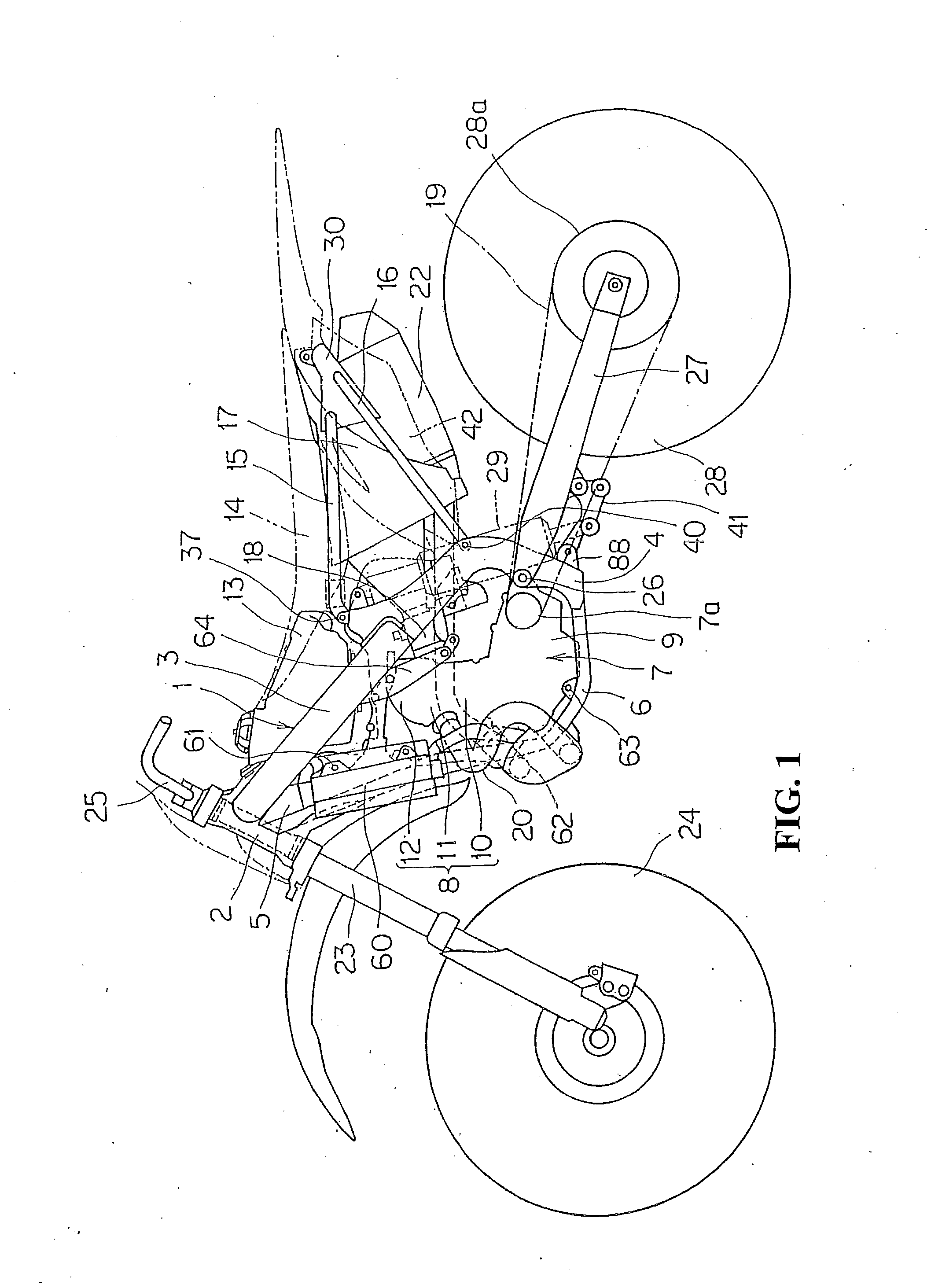
[0033]FIG. 1 is a side view of an offroad motorcycle according to an embodiment of the present invention.

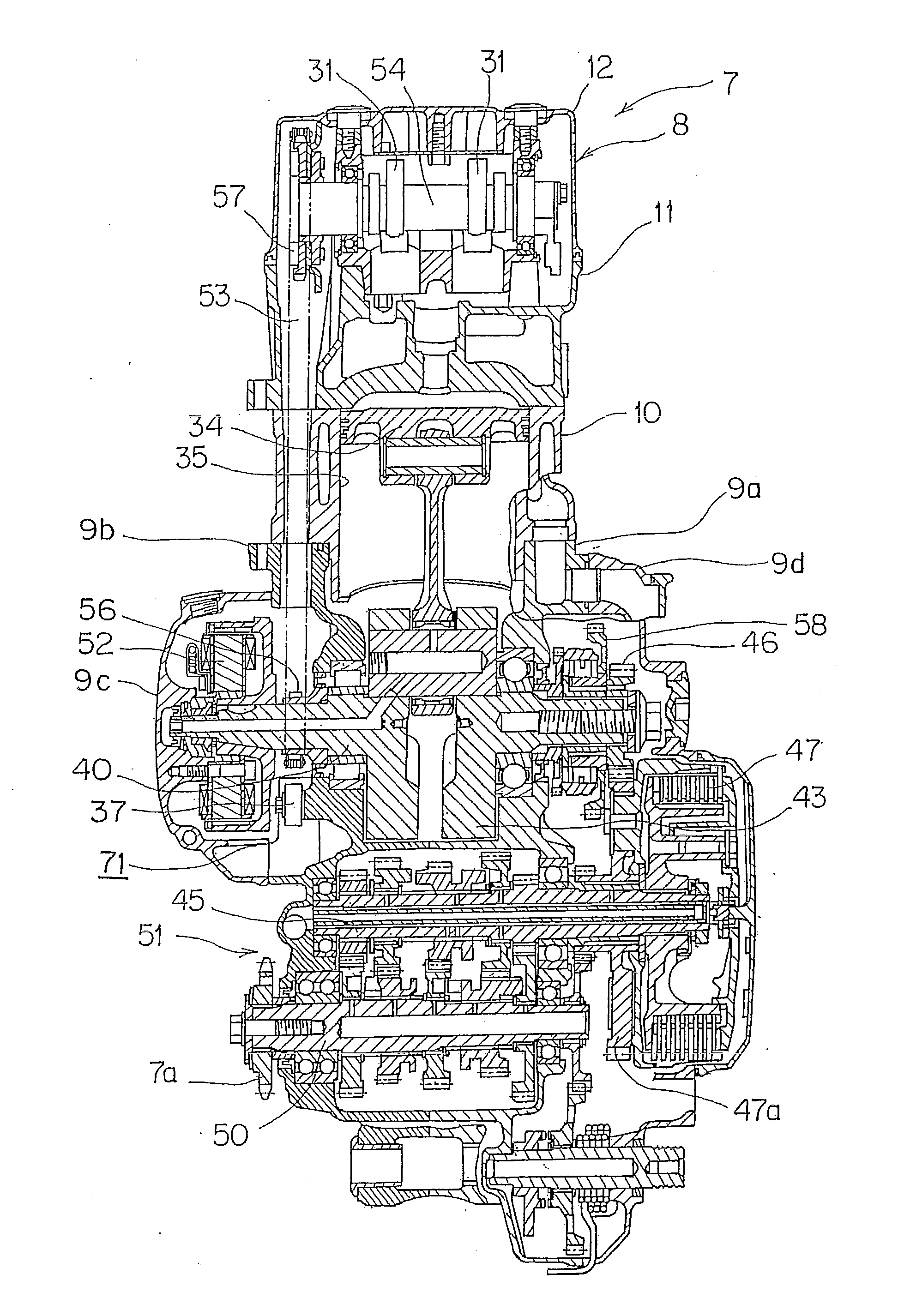
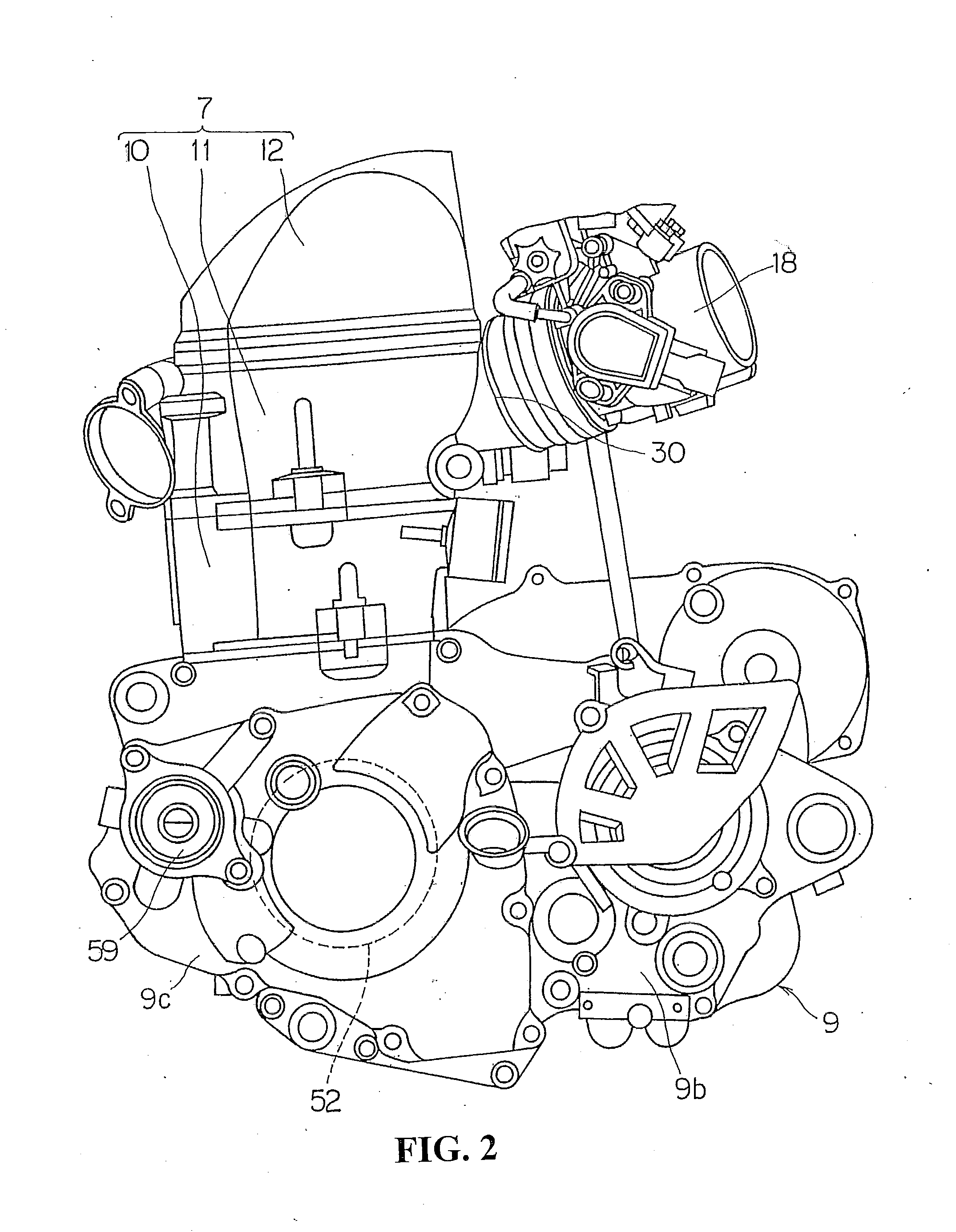
[0034]A body frame 1 of this motorcycle includes a head pipe 2, main frames 3, center frames 4, a down frame 5 and lower frames 6, which are connected to one another in a loop form, and an engine 7 is supported on the inside thereof. The engine7 has a cylinder 8 and a crankcase 9. The main frames 3, the center frames 4 and the lower frames 6 are provided in left-right pairs, whereas the head pipe 2 and the down frame 5 are provided as single members along the center of the vehicle body.

[0035]The main frames 3 extend over the engine 7 rectilinearly and downwardly rearwards...


PUM


Abstract

An internal combustion engine for reducing the amount of bubbles contained in the circulated oil without reducing the ground clearance of the engine. A crankcase is provided therein with an oil suction passage makes an oil pump and an end part of a bottom wall of an oil sump chamber communicate with each other, passes between the oil sump chamber and a hanger boss, and has a lowest part located below the bottom wall of the oil sump chamber.

Description

[0001]The present application claims priority under 35 USC 119 to Japanese Patent Application No. 2008-197884 filed on Jul. 31, 2008 the entire contents of which are hereby incorporated by reference.BACKGROUND OF THE INVENTION[0002]1. Field of the Invention[0003]The present invention relates to an internal combustion engine having a lubrication structure for circulating an oil.[0004]2. Background Art[0005]An internal combustion engine is known with a lubrication structure for circulatorily supplying an oil to sliding parts. In such an internal combustion engine, a structure has been adopted in which the oil is supplied to the sliding parts (e.g., a generator, a crankshaft, etc.) by use of an oil pump. The oil having lubricating the sliding parts flows down into an oil sump chamber provided at a lower part of the crankcase. The oil having flowed down into and reserved in the oil sump chamber is pumped up by the oil pump, and is again circulatorily supplied to the sliding parts. See, ...

Claims


Application Information

Patent Timeline
Patent Type & Authority Applications(United States)
IPC IPC(8): F01M1/02
CPCF01M1/12F01M11/0004F01M2011/0083F01M2011/0066F01M2001/126
Inventor YASUI, SHINSUKETSUBAKINO, YUKIHIROSHINDOME, KAZUYAAZUMAGAKITO, ISAOSENDA, AKIO
Owner HONDA MOTOR CO LTD
Why Eureka
Try Eureka