
Drive unit and electric-motor-assisted bicycle

a technology of electric motors and drives, applied in the direction of clutches, freewheel clutches, vehicle components, etc., can solve the problems of limiting the arrangement of rear suspension and battery, limiting the manner in which the rear suspension and battery can be arranged, and the substrate size is large, so as to increase the size of the housing.

Active Publication Date: 2017-12-05
YAMAHA MOTOR CO LTD
View PDF16 Cites 2 Cited by
  • Summary
  • Abstract
  • Description
  • Claims
  • Application Information

AI Technical Summary

Benefits of technology

[0008]A plurality of circuits or circuit elements are mounted on the substrate to control the operation of the motor. To achieve this, it is preferable that the substrate includes a component side (or component sides) that is / are as large as possible. However, substrates with larger component sides have increased substrate sizes. A substrate of large size limits how the other components in the housing may be arranged. If a sufficient degree of freedom in terms of how to arrange the components in the housing is to be provided, the size of the housing may increase.
[0009]As discussed above, the drive unit is attached to the bottom of the vehicle-body frame. Thus, larger housing sizes may reduce minimum ground clearance (i.e., a distance between the drive unit and the ground), increase Q Factor, or increase rear / center length. Larger housing sizes may also limit the manner in which the rear suspension and battery are able to be arranged.
[0010]Preferred embodiments of the present invention reduce the size of the housing of the drive unit included in an electric-motor-assisted bicycle.

Problems solved by technology

A substrate of large size limits how the other components in the housing may be arranged.
Larger housing sizes may also limit the manner in which the rear suspension and battery are able to be arranged.

Method used


Image

  • Drive unit and electric-motor-assisted bicycle
  • Drive unit and electric-motor-assisted bicycle
  • Drive unit and electric-motor-assisted bicycle

Examples


Embodiment Construction

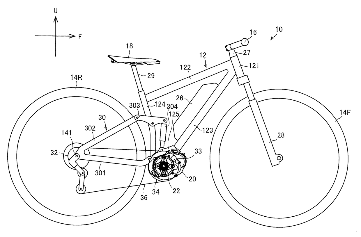
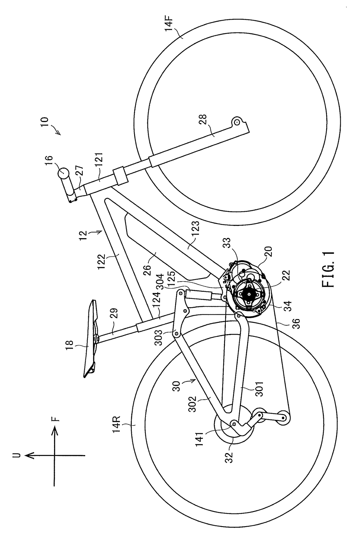
[0021]The present inventors conducted extensive research to find a way to reduce the size of the housing of the drive unit. The inventors focused on how the various components of the drive unit may be arranged.

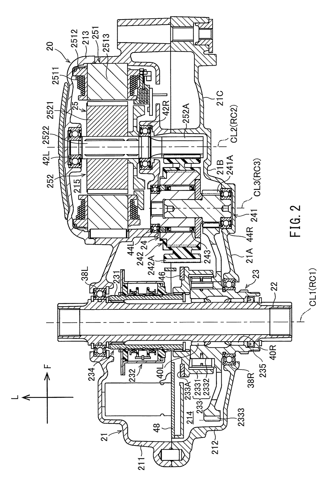
[0022]A drive unit according to a preferred embodiment of the present invention preferably includes a housing, a crank axle, a motor, and a reduction gear. The housing is attached to the vehicle-body frame. The crank axle extends through the housing in the left-to-right direction with respect to the vehicle. The motor is housed in the housing. The reduction gear is housed in the housing and transmits driving forces from the motor to a resultant-force output axle through which the crank axle is extended.

[0023]The output shaft of the motor and the rotatable shaft of the reduction gear are positioned to be parallel or substantially parallel to the crank axle. An output gear on the output shaft of the motor engages the reduction gear. The reduction gear engages the driven gear of ...


PUM


Abstract

In a drive unit in an electric-motor-assisted bicycle, as viewed in an axial direction of the crank axle, a substrate housed in a housing does not overlap a reduction gear but overlaps a driven gear. The substrate is disposed around the crank axle and includes a component side extending in a direction crossing the central axis of the crank axle. The substrate extends in directions crossing radial directions of the crank axle. One end of the substrate in the direction in which the substrate extends is located on the side of the straight line connecting the shaft center of the crank axle and the shaft center of the motor output shaft as viewed in the axial direction, that is opposite to the side having the other end of the substrate in the direction in which the substrate extends.

Description

CROSS REFERENCE TO RELATED APPLICATIONS[0001]This application claims the benefit of priority to Japanese Patent Application No. 2016-091469 filed on Apr. 28, 2016. The entire contents of this application are hereby incorporated herein by reference.BACKGROUND OF THE INVENTION[0002]1. Field of the Invention[0003]The present invention relates to drive units and electric-motor-assisted bicycles, and more particularly to a drive unit attached to a vehicle-body frame included in an electric-motor-assisted bicycle and an electric-motor-assisted bicycle including such a drive unit.[0004]2. Description of the Related Art[0005]Bicycles are used by many people, regardless of age and gender, as a handy transportation means. In recent years, electric-motor-assisted bicycles that add driving forces from the motor to pedaling forces from the rider to assist the rider have become popular. Such an electric-motor-assisted bicycle is disclosed in JP 2014-196080 A, for example.[0006]JP 2014-196080 A de...

Claims


Application Information

Patent Timeline
Patent Type & Authority Patents(United States)
IPC IPC(8): B62M6/55B62M6/50F16D41/24
CPCB62M6/55F16D41/24B62M6/50B62M6/40B62M11/02
Inventor UDA, MASATSUGUSUZUKI, RYOTAMANO, YASUNORIUSAMI, TOMOHIRO
Owner YAMAHA MOTOR CO LTD
Learn More