Device for Separating Oil From Blow-By Gas

a technology of blow-by gas and separator, which is applied in the direction of liquid degasification, separation processes, machines/engines, etc., can solve the problems of reducing pressure, leaking compressed gas under high pressure into the crank case, and creating problems, etc., and achieves the effect of streamlined flow

Active Publication Date: 2010-01-28
HYUNDAI MOTOR CO LTD +1
View PDF8 Cites 2 Cited by
  • Summary
  • Abstract
  • Description
  • Claims
  • Application Information

AI Technical Summary

Benefits of technology

[0020]A protrusion may be formed on inside wall of the blow-by gas passage in order to separate the oil from the blow-by gas. The protrusion may be inclined in the forward direction of the blow-by gas so that contact surface with flow is increased and thus streamlined flow is achieved.

Problems solved by technology

The blow-by gas creates some problems, which are more severe in a diesel engine than in a gasoline engine.
This is because, in case of the diesel engine having a high compression ratio, compressed gas under high pressure leaks into the crank case from the cylinder through the gap between the cylinder and the piston.
Especially, in a diesel engine using a turbocharger, when a blow-by gas outlet of the crank case or the cylinder head is directly connected to a suction passage, high negative suction pressure increases flow rate thereby lowering pressure, so that the blow-by gas is rapidly absorbed from the crank case into the suction side, thereby dropping the pressure inside the crank case to be abnormally low.
This as a result can cause critical damages to the quality and endurance of the engine.
For example, the consumption of engine oil sharply increases, oil leaks from respective seals, or dust is introduced into the engine.
However, the method of separating engine oil using the baffle or the nonwoven cloth does not sufficiently separate the oil and thus is not suitable to be used in consideration of latest emission regulations, which are getting gradually stronger.
Furthermore, the external separator mounted on the head cover increases the size of the engine, thereby making it difficult to design the engine to be compact.

Method used


Image

  • Device for Separating Oil From Blow-By Gas
  • Device for Separating Oil From Blow-By Gas
  • Device for Separating Oil From Blow-By Gas

Examples


Embodiment Construction

[0027]Reference will now be made in detail to various embodiments of the present invention(s), examples of which are illustrated in the accompanying drawings and described below. While the invention(s) will be described in conjunction with exemplary embodiments, it will be understood that present description is not intended to limit the invention(s) to those exemplary embodiments. On the contrary, the invention(s) is / are intended to cover not only the exemplary embodiments, but also various alternatives, modifications, equivalents and other embodiments, which may be included within the spirit and scope of the invention as defined by the appended claims.

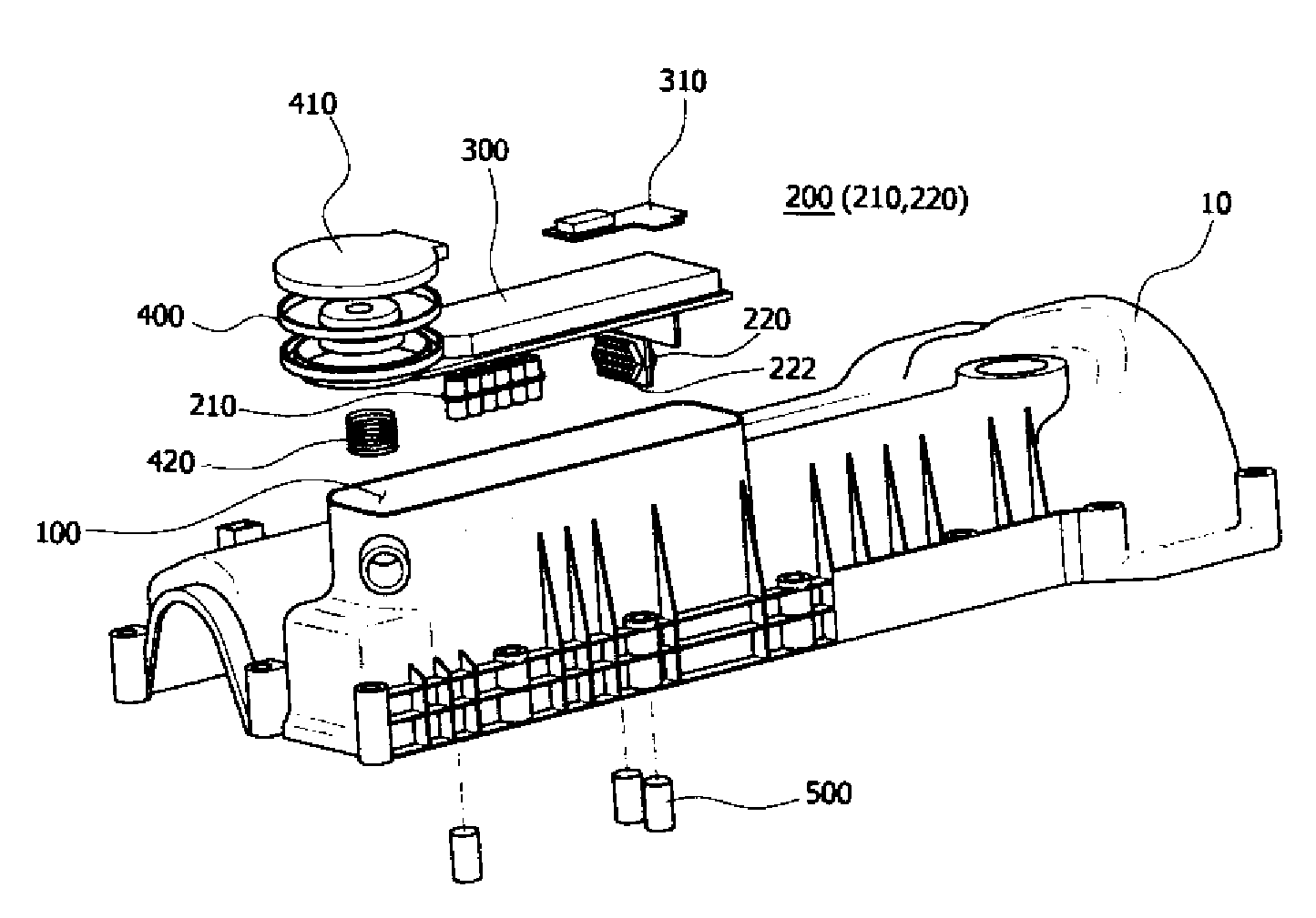
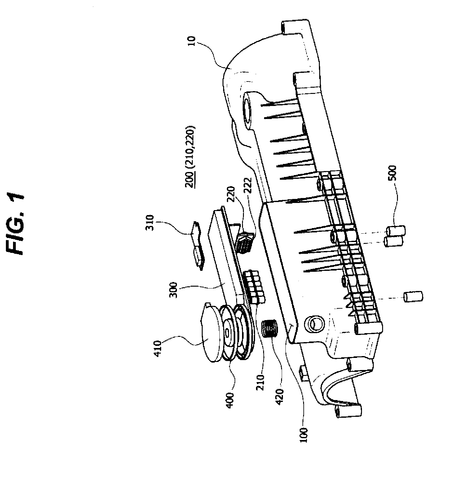
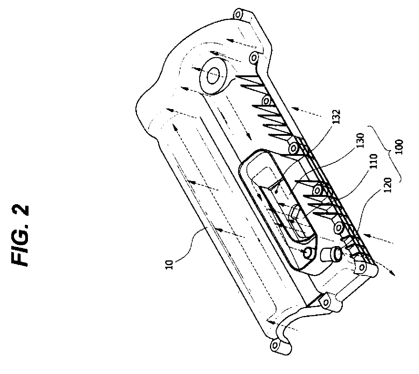
[0028]FIG. 1 is an exploded perspective view illustrating a device for separating oil according to various aspects of the present invention, and FIG. 2 is a perspective view illustrating the configuration of a blow-by gas passage of the device for separating oil according to various aspects of the present invention.

[0029]As shown in F...


PUM

PropertyMeasurementUnit
flow rateaaaaaaaaaa
angleaaaaaaaaaa
compression ratioaaaaaaaaaa

Abstract

A device for separating oil includes a blow-by gas passage provided to a head cover to discharge blow-by gas introduced from an engine and a separator coupled to the blow-by gas passage to separate oil from the blow-by gas. The device for separating oil from blow-by gases can effectively separate oil from the blow-by gas. Since the blow-by gas passage for discharging the blow-by gas is provided to the head cover, a hose or a pipe is not required to carry the blow-by gas, and thereby the engine can be designed to be compact.

Description

CROSS-REFERENCE TO RELATED APPLICATION[0001]The present application claims the priority to Korean Patent Application No. 10-2008-0073090 on Jul. 25, 2008, the entire contents of which application is incorporated herein for all purposes by this reference.BACKGROUND OF THE INVENTION[0002]1. Field of the Invention[0003]The present invention relates to a device for separating oil from blow-by gases, and more particularly, to a device for separating oil, which is integrally provided to a head cover of an engine so as to make the engine be compact and also to improve oil separating efficiency.[0004]2. Description of Related Art[0005]Emissions from automobiles are generally divided into three types according to their sources: exhaust gas produced through the combustion of fuel-air mixture in a cylinder and exhausted via an exhaust system; evaporation gas evaporated from fuel in a fuel tank; and blow-by gas, such as a portion of the fuel-gas mixture or unburned gas, which has leaked into a ...

Claims


Application Information

Patent Timeline
Patent Type & Authority Applications(United States)
IPC IPC(8): B01D19/00F02B77/02
CPCF01M13/0416F01M11/08F01M13/00F01M13/04
Inventor SONG, KYE OONG
Owner HYUNDAI MOTOR CO LTD
Why Eureka
Try Eureka