Landing gear

Inactive Publication Date: 2009-04-02
AIRBUS OPERATIONS LTD
View PDF34 Cites 2 Cited by
  • Summary
  • Abstract
  • Description
  • Claims
  • Application Information

AI Technical Summary

Benefits of technology

[0032]The present invention also provides a method of reducing noise caused by landing gear on an aircraft including a step of manufacturing a landing gear according to any aspects of the invention as described herein. The method may for example include a step of modifying an existing design in order to reduce noise caused by the landing gear.
[0033]There is yet further provided a method of flying an aircraft during the approach on landing of the

Problems solved by technology

A significant amount of noise is generated by the interaction of the aircraft and the air flowing past it, which results in turbulent flows and consequently noise.
During appr

Method used


Image

  • Landing gear
  • Landing gear
  • Landing gear

Examples


Example

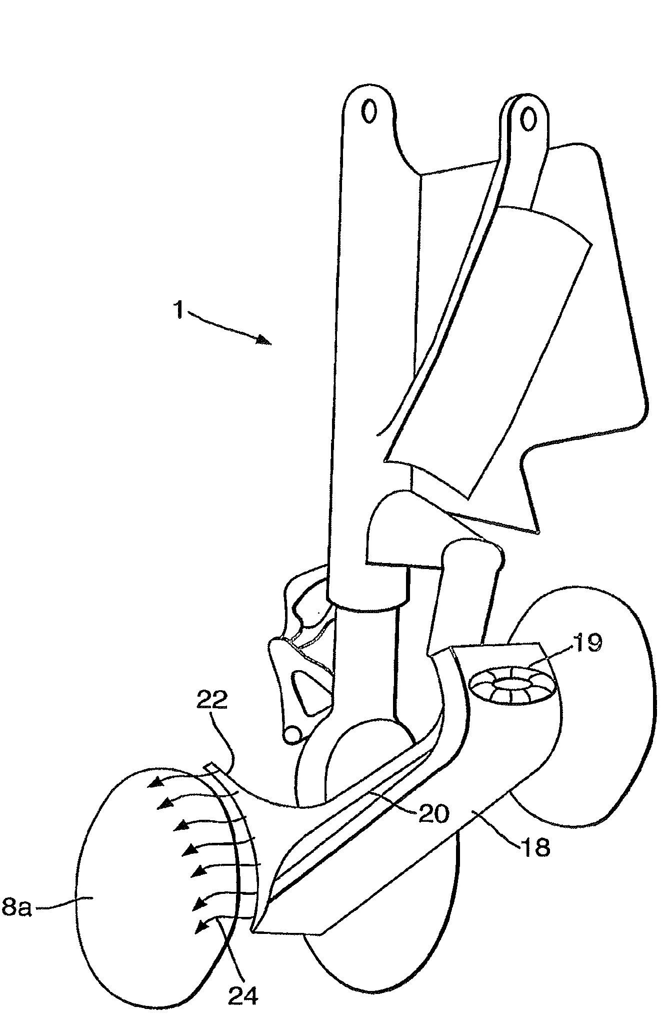
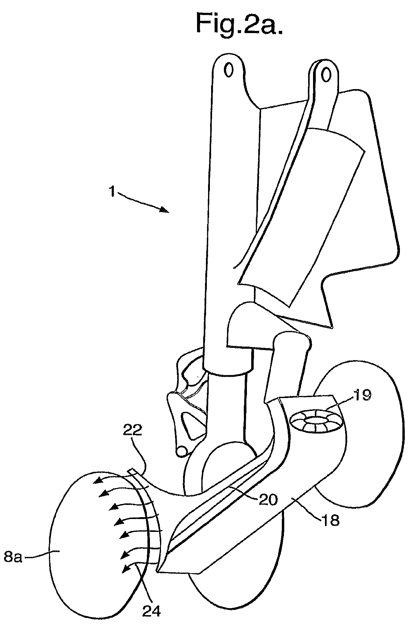
[0045]According to a second embodiment, shown in FIGS. 2a and 2b there is provided an aircraft main landing gear 1 with an undertray 18 fitted. The undertray 18 includes a fairing 11 that has a central air intake vent 19, that is connected via an air duct 20 to an air exhaust 22. The air intake vent 19 is positioned at the stagnation point on the leading edge of the undertray 18 and is in the form of a ram air intake. The air intake 19, air duct 20, and air exhaust 22 of the fairing are illustrated schematically in FIG. 2b. As can be seen in FIG. 2b, the air duct 20 includes a narrowed region 23 that acts as a venturi tube. During flight, air enters the intake 19 and is directed down the duct 20. The airflow speeds up as it flows through the venturi tube 23 and the air then exits with high speed from the exhaust 22. The exhaust 22 is shaped as a diffuser that causes the air to exit in the form of an air curtain 24 (see FIG. 2a), which acts as a virtual (air) fairing. The air exhaust...

Example

[0046]A third embodiment of the invention is illustrated schematically by FIG. 2c. The third embodiment operates in a manner very similar to that of the second embodiment, in that an air curtain 24 is formed by means of a fairing 18 having a ram air intake 19 and an air exhaust 22. However, the third embodiment differs from the second, in that the air curtain 24 is not formed by the air exhausted from the air exhaust 22; instead (as can be seen in FIG. 2c) an extra intake opening is provided in the form of a diffuser intake 25, which forms the air curtain 24. The operation of the fairing 18 of the third embodiment may be understood as follows. Air enters the ram air intake 19, passes along the duct 20 and increases in speed as it flows through the venturi tube 23 and then passes out of the exhaust 22 with very high speed. The air pressure just beyond the venturi tube 23 is, as a result of the high speed airflow, lower than the exterior of the fairing 18 and thus, air is drawn throug...


PUM


Abstract

An aircraft landing gear is arranged such that in its deployed position it is configured to reduce, during the approach on landing, the noise generated by the interaction of the landing gear and the air flowing past the landing gear. Various means are described to reduce the amount of turbulent air flow generated in the region of the landing gear, including inverting and fairing the nose-gear shock-absorbing leg, providing faired twin in-line oleos and providing fairings that produce shielding air curtains.

Description

RELATED APPLICATIONS[0001]This application is a continuation of application Ser. No. 10 / 551,939 filed Oct. 5, 2006, which in turn claims priority to Application No. PCT / GB2004 / 001525 filed Apr. 7, 2004, which in turn claims priority to Application No. GB 0308003.3 filed Apr. 7, 2003, and also related is Application No. EP 03252216.1 filed Apr. 8, 2003, all of which are hereby fully incorporated herein by reference.BACKGROUND OF THE INVENTION[0002]The present invention relates to reducing aircraft noise. In particular, the invention relates to landing gear designed to reduce the noise generated by the interaction of the landing gear and the air flowing past it during flight, especially during the approach of the aircraft on landing.[0003]It is desirous to reduce the noise generated by aircraft, for example, to lessen disruption or inconvenience, resulting from aircraft noise, caused to the public on the ground near airports. A significant amount of noise is generated by the interacti...

Claims


Application Information

Patent Timeline
IPC IPC(8): B64C25/10B64C7/00B64C25/00
CPCB64C7/00B64C2025/003B64C25/001
Inventor WOOD, CHRISTOPHER NEIL
Owner AIRBUS OPERATIONS LTD
Why Eureka
Try Eureka