High pressure dome check valve

a check valve and high-pressure dome technology, applied in the field of check valves, can solve problems such as inhibiting or checking the flow of fluid, and achieve the effects of reducing the potential for air entrapment, and increasing the resistance to high backpressur

Active Publication Date: 2018-05-22
HALKEY ROBERTS CORP
View PDF17 Cites 7 Cited by
  • Summary
  • Abstract
  • Description
  • Claims
  • Application Information

AI Technical Summary

Benefits of technology

[0018]The valve element of the valve is self-supporting and when assembled in the valve, exerts a predetermined pressure against the valve seat thus sealing the valve. The element deflects at the center after pressure rises over the predetermined cracking pressure or by being accessed by a syringe or other device, thus opening the bi-directional flow path.
[0019]Unlike the prior art dome check valves noted above, the dome of the valve element includes cut-outs for additional fluid flow, thereby streamlining flow while reducing the potential for air entrapment. The underside of the dome-shaped valve element also includes a thickened concave undersurface and thickened support legs to significantly increase the resistance to high backpressures, while also minimizing potential air entrapment that might otherwise occur underneath the prior art dome check valves noted above.
[0020]The valve housing is manufactured in a modular fashion, allowing the assembly of the same valve element into various housings having different connecting arrangements, such as ML, MLL, tubing fitment or barbed connector. The components are producible reliably by high cavitation molds and are suitable for high speed assembly process, thereby resulting in a highly economical valve. None of the valve components require registration radially during assembly.

Problems solved by technology

In the opposite direction, however, the fluid pressure along with the spring forces the valve stem against a valve seat, thereby inhibiting, or checking the flow of fluid therethrough.

Method used


Image

  • High pressure dome check valve
  • High pressure dome check valve
  • High pressure dome check valve

Examples


Embodiment Construction

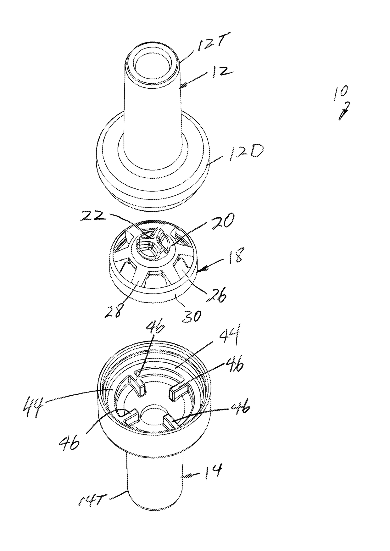
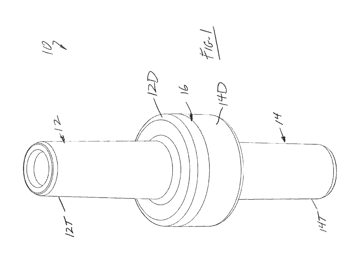
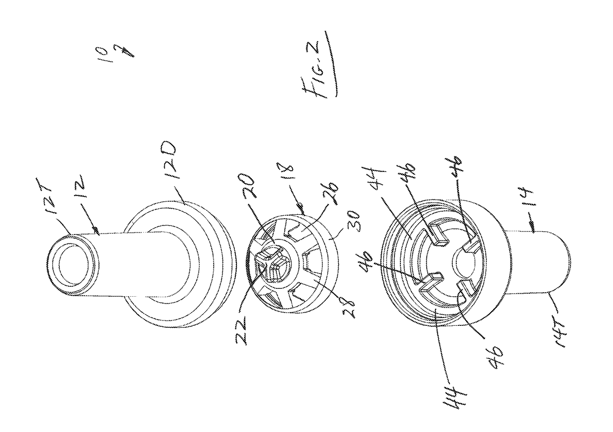
[0032]As best shown in FIG. 1, the valve 10 of the invention comprises inlet housing 12 and an outlet housing 14 fastened, preferably permanently, together at joint 16 such as by welding or bonding. The inlet and outlet housing 12&14 include tube fittings 12T and 14T respectively; however, it shall be appreciated that the housing 12&14 may include other types of fittings such as a luer lock fitting without departing from the spirit and scope of this invention. For example, one or both of the inlet and outlet housings 12&14 may be provided with barbed hose fittings, luer fittings or locking luer fitting (see the various embodiments in the Dome Check Valves of U.S. Pat. Nos. 7,296,782 and 7,641,174 cited above). Both the inlet and outlet housing 12&14 further include a generally dome-shaped larger diameter configuration 12D and 14D respectively, that are appropriately configured to mate together to then be fastened at joint 16.

[0033]As shown in FIGS. 2 and 3, an elastomeric dome-shape...


PUM


Abstract

A check valve including an elastomeric valve element having a dome-shaped configuration that seals in its at-rest position occluding fluid flow in both directions. The dome-shaped elastomeric valve element is constructed in such a way to be deflectable, such as being activated by the external device such as a male luer whereupon the valve is cracked open to become a two-way valve allowing flow in both directions. The valve element may also be cracked open by sufficient fluid pressure in its inlet. The valve element is self-aligning. The dome-shaped of the valve element includes cut-outs for additional fluid flow, thereby streamlining flow while reducing the potential for air entrapment. The underside of the dome-shaped valve element also includes a thickened concave undersurface and thickened support legs to significantly increase the resistance to high backpressures, while also minimizing potential air entrapment.

Description

CROSS-REFERENCE TO RELATED INVENTIONS[0001]This application claims the benefit of provisional application No. 62 / 151,497, filed Apr. 23, 2015, the disclosure of which is hereby incorporated by reference herein.BACKGROUND OF THE INVENTION[0002]Field of the Invention[0003]This invention relates to check valves, and relates more specifically to a check valve for medical usage.[0004]Description of the Background Art[0005]Presently, there are many types of check valves which are designed to control the one-way flow of a fluid therethrough. One common type of check valve comprises a valve element, such as a ball or spring biased valve stem, reciprocatingly positioned within a valve body providing a fluid passageway. The flow of fluid in one direction through the valve body is permitted upon displacement of the stem as it flows around the valve stem to exit the valve body. In the opposite direction, however, the fluid pressure along with the spring forces the valve stem against a valve sea...

Claims


Application Information

Patent Timeline
Patent Type & Authority Patents(United States)
IPC IPC(8): F16K15/14A61M39/24A61M39/26
CPCF16K15/141A61M39/24A61M39/26F16K15/144F16K15/145F16K15/147Y10T137/7895A61M2039/246A61M2039/2406A61M2039/2433A61M2039/2446A61M2039/2493Y10T137/784A61M2039/242
Inventor STANTON, KATHERINE J.BELLO, STEPHEN P.
Owner HALKEY ROBERTS CORP
Why Eureka
Try Eureka