
Holographic Projection System Using Micro-Mirrors for Light Modulation

a technology of light modulation and projection system, applied in the field of holographic projection system, to achieve the effect of high resolution, low noise, and sufficient resolution and brightness

Inactive Publication Date: 2010-01-21
SEEREAL TECHNOLOGIES
View PDF7 Cites 69 Cited by
  • Summary
  • Abstract
  • Description
  • Claims
  • Application Information

AI Technical Summary

Benefits of technology

[0021]It is the object of the present invention to find among the known light modulator means for modulating a light wave front with the help of discretely controllable modulator cells which have electromechanically movable micro-mirror surfaces those types which if used in a holographic projection system provide a high-quality holographic representation, in particular sufficient resolution and brightness if there is a rapidly changing sequence of video holograms of the moving three-dimensional scene. At the same time, the invention aims to identify the technical means which are necessary to take advantage of such light modulator means in a projection system for a high-quality holographic reconstruction, in particular in order to realise a high resolution and low noise while there is a rapidly changing sequence of video holograms.
[0028]The phase modulation behaviour of the above-mentioned diffraction grating light modulators is particularly well suited for the holographic reconstruction of three-dimensional scenes, because of the fast operating speed of the micro-mirrors and thanks to the fact that a great resolution can be realised inexpensively.

Problems solved by technology

A technical problem when realising such light modulators, however, are the fix micro-mirror surfaces of the controllable diffraction gratings, which are disposed between the moved micro-mirror surfaces.

Method used


Image

  • Holographic Projection System Using Micro-Mirrors for Light Modulation
  • Holographic Projection System Using Micro-Mirrors for Light Modulation
  • Holographic Projection System Using Micro-Mirrors for Light Modulation

Examples


Embodiment Construction

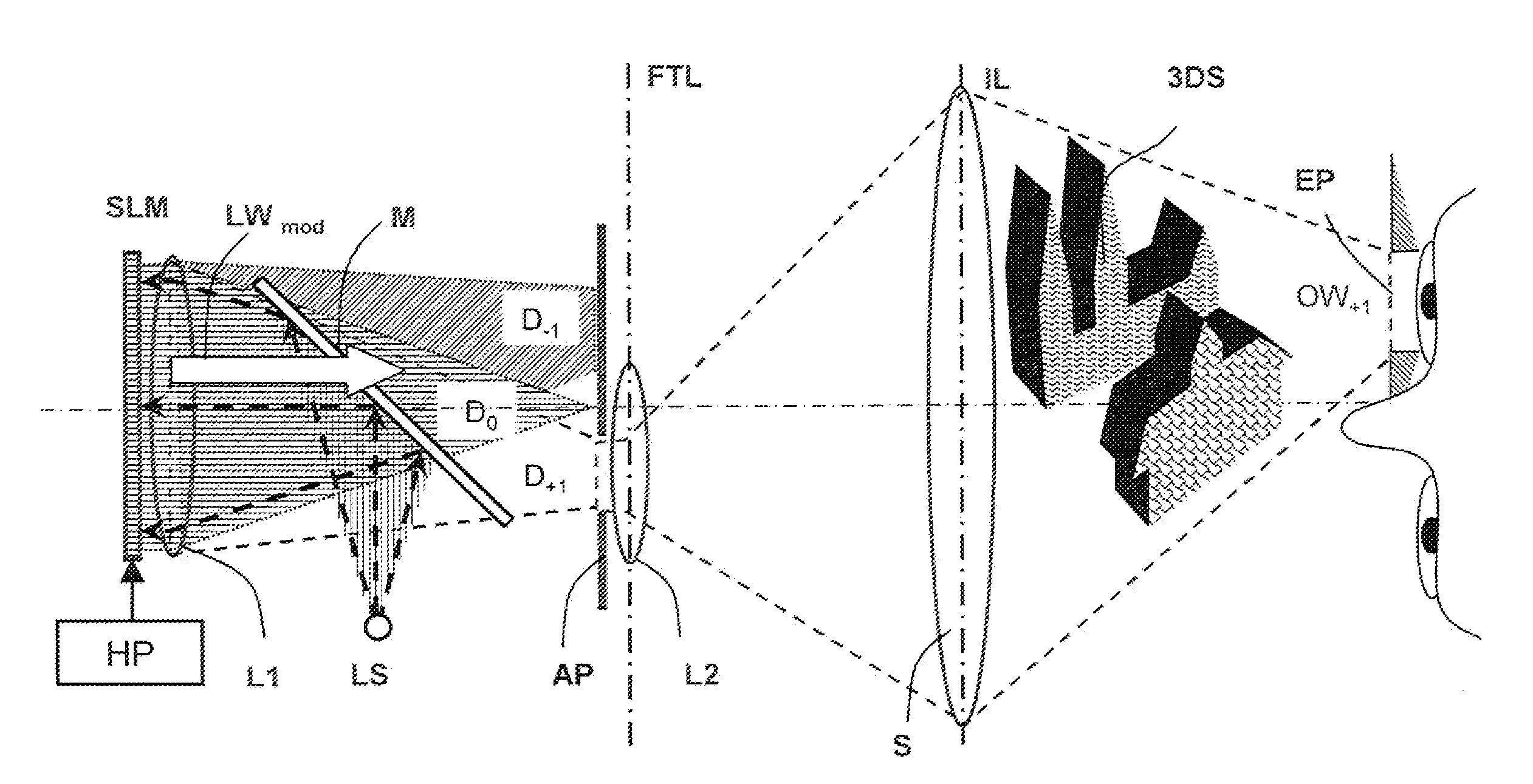
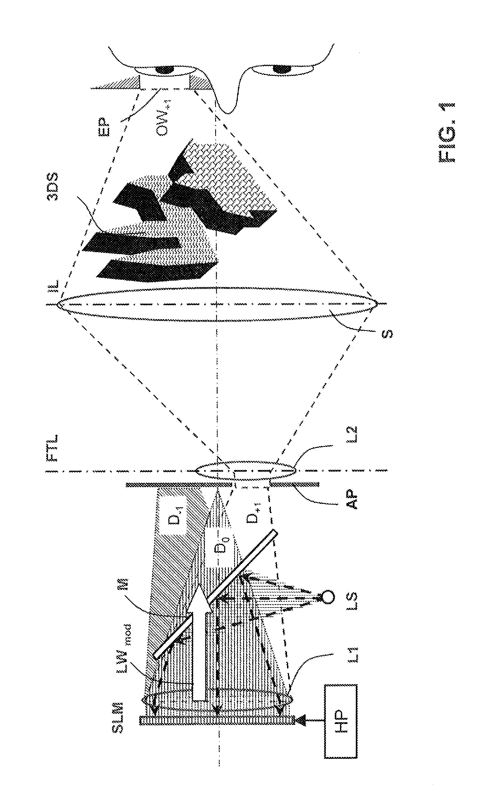
[0039]FIG. 1 shows a holographic projection system with light modulator means, which contains a diffraction grating light modulator SLM. The light modulator SLM has a modulator surface with modulator cells, which are integrally formed on the substrate of a control circuit in the form of a micro-mirror structure, and which form separately controllable diffraction gratings. In the present case, the light modulator SLM is one of the prior art diffraction grating light modulators with a plurality of electromechanically movable micro-mirror surfaces for each modulator cell, said surfaces being controlled with the help of holographic input information.

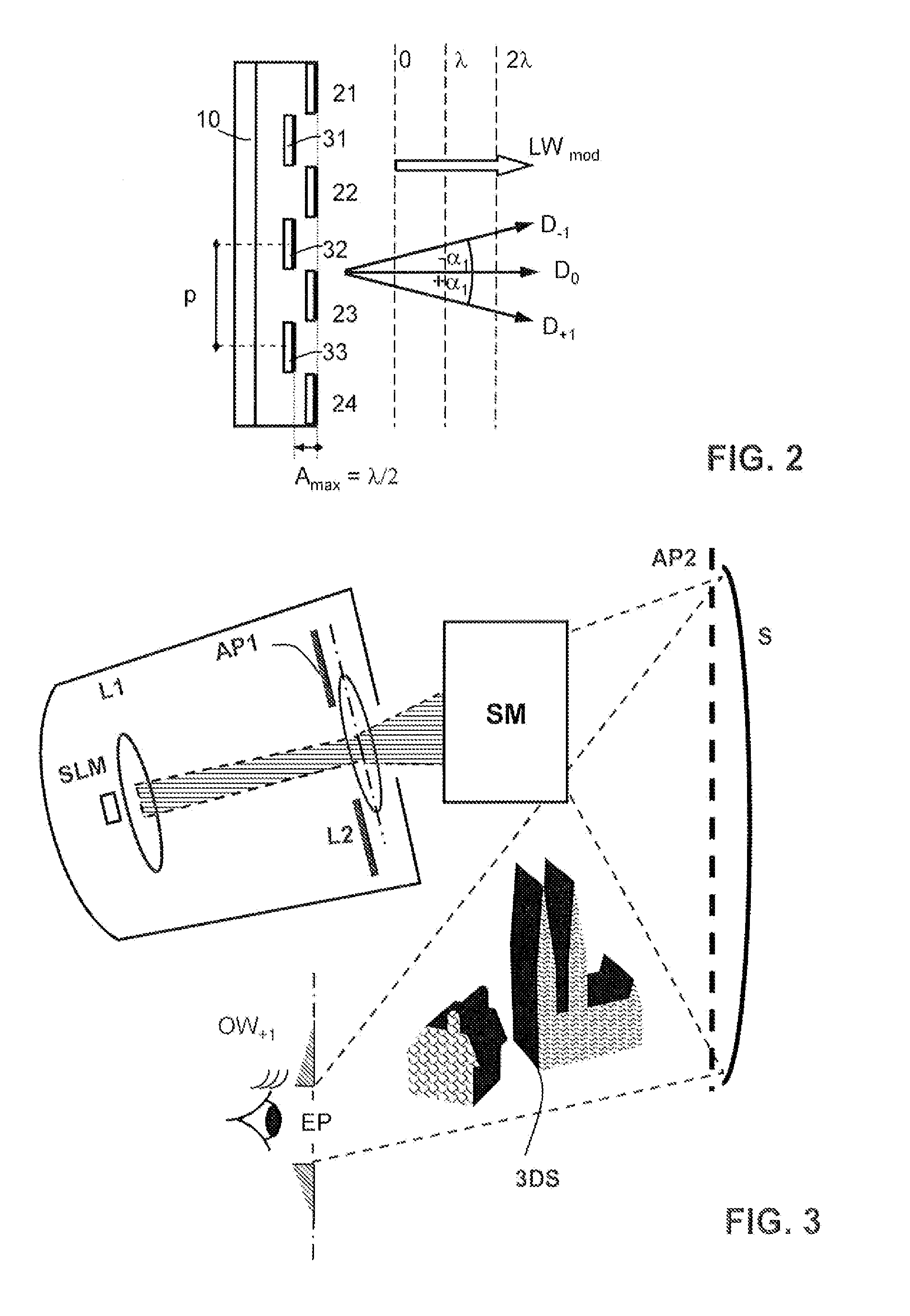
[0040]In order to achieve a high-quality holographic reconstruction, it must be possible to lower the diffraction grating amplitude A of the micro-mirrors of each modulator cell at least up to half a light wavelength λ. Because the light modulator SLM operates in the reflective mode, the modulator cells can thus set any desired local phase v...


PUM


Abstract

The invention relates to a holographic projection system wherein light modulator means SLM with electromechanically moved micro-mirrors modulate a light wave front LWmod. According to the invention, a hologram processor HP sets micro-mirror surfaces of prior art spatial light modulator which are disposed as controllable diffraction gratings on a substrate of a control circuit, such that they reach a certain diffraction grating amplitude, by moving them continuously at right angles to the substrate, said diffraction grating amplitude being dependent on the content of a sequence of video holograms. The diffraction grating modulate a light wave which is emitted by the light modulator means and which generates illumination capable of generating interference according to a phase hologram, so that the modulated light wave is used directly for the holographic reconstruction.

Description

FIELD OF THE INVENTION[0001]The present invention relates to a holographic projection system which contains light modulator means with individually controllable modulator cells in the form of electro-mechanically movable micro-mirrors, i.e. a so-called electro-mechanical system (MEMS), for modulating a light wave front. The modulator cells are illuminated by light capable of generating interference, and they are coded with sequences of video holograms in order to reconstruct holographically the optical appearance of three- dimensional scenes. The system shall be used predominantly to reconstruct a moving three-dimensional scene with holographic video means in real time or at least near real time. This makes particularly great demands on the resolution and speed of the light modulator means in order to be able to realise holographic reconstructions with high resolution, brightness and contrast while there is only little local and temporary cross-talking. Because in the micro-mechanic...

Claims


Application Information

Patent Timeline
Patent Type & Authority Applications(United States)
IPC IPC(8): G02B5/32
CPCG02B26/0808G03H1/02G03H1/2294G03H2001/221G03H2225/60G03H2225/23G03H2225/24G03H2225/32G03H2225/52G03H2225/11
Inventor HAUSSLER, RALFSCHWERDTNER, ARMIN
Owner SEEREAL TECHNOLOGIES
Learn More