
Dye-sensitized solar cell and method of manufacturing same

Inactive Publication Date: 2010-01-21
LAPIS SEMICON CO LTD
View PDF6 Cites 1 Cited by
  • Summary
  • Abstract
  • Description
  • Claims
  • Application Information

AI Technical Summary

Benefits of technology

[0018]It is one object of the present invention to provide a method for readily fabricating a dye-sensitized solar cell having a porous layer of increased thickness.
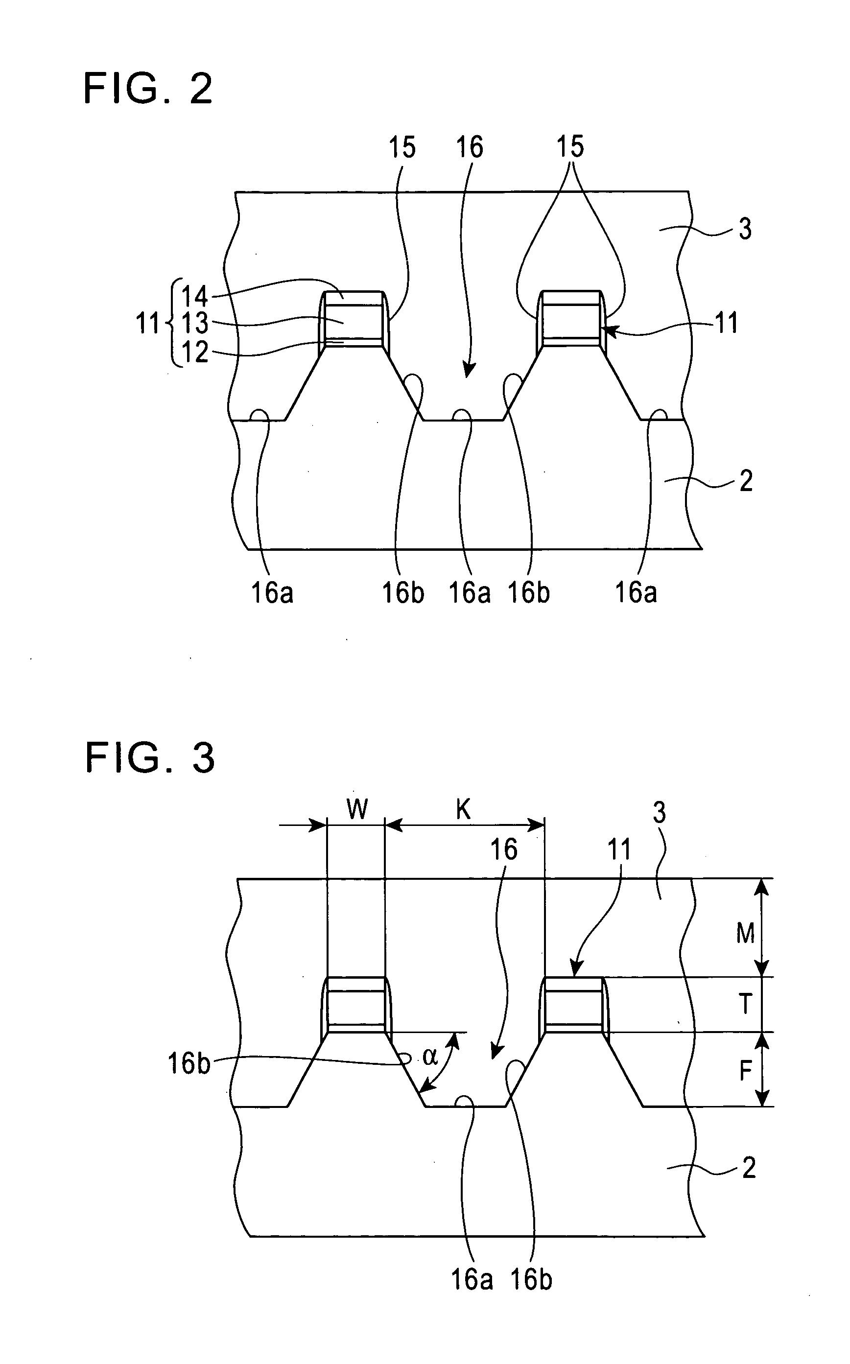
[0021]Because the porous layer fills the trench, the porous layer is substantially thickened as a whole, and the amount of sensitizing dye adsorbed thereon is increased without changing the thickness of the collecting electrode traces and without narrowing the entrance through which light enters via the glass substrate. Thus, it is possible to readily provide a dye-sensitized solar cell having a thicker porous layer and having an improved photoelectric-conversion efficiency.

Problems solved by technology

Otherwise, it would logically be impossible to capture all of the excited electrons.

Method used


Image

  • Dye-sensitized solar cell and method of manufacturing same
  • Dye-sensitized solar cell and method of manufacturing same
  • Dye-sensitized solar cell and method of manufacturing same

Examples


Embodiment Construction

[0029]An embodiment of a dye-sensitized solar cell according to the present invention and a method for manufacturing the same is described below with reference to the accompanying drawings.

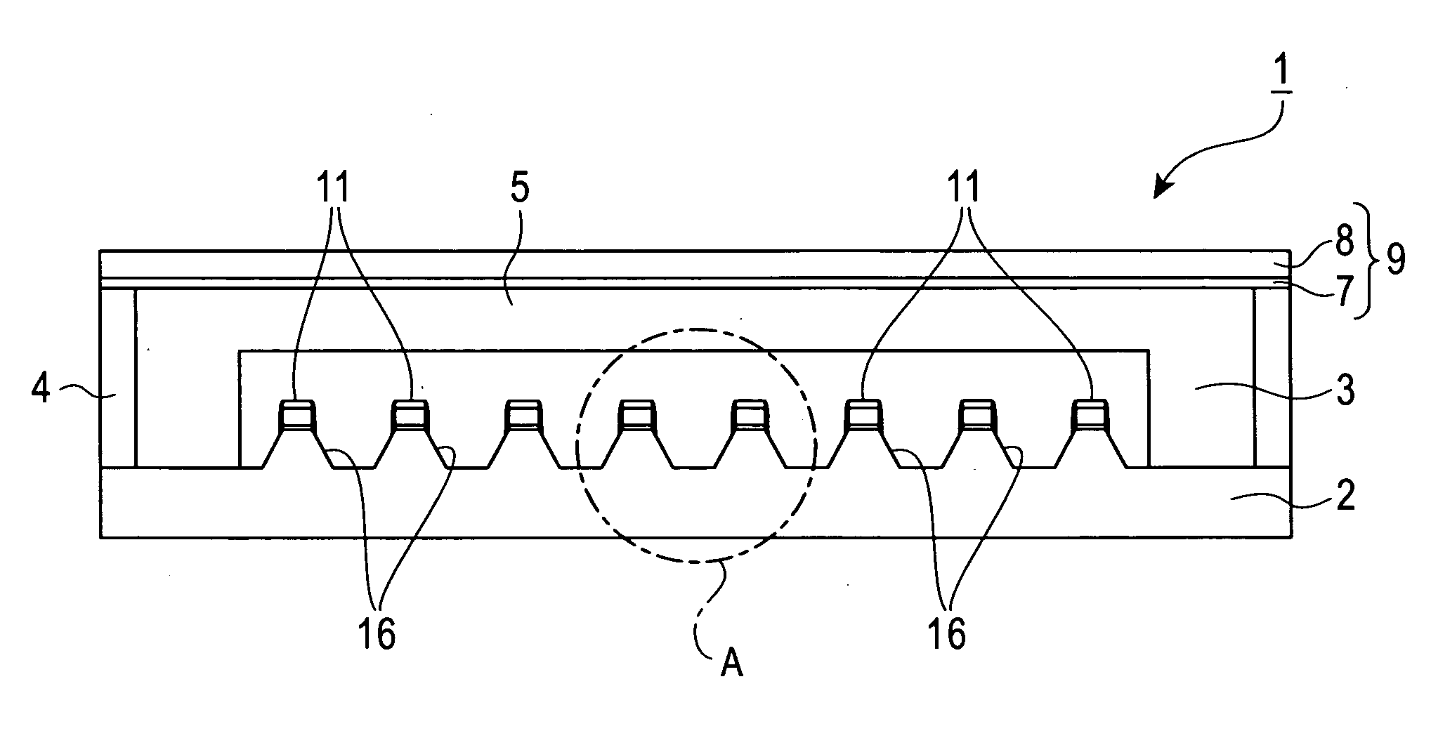
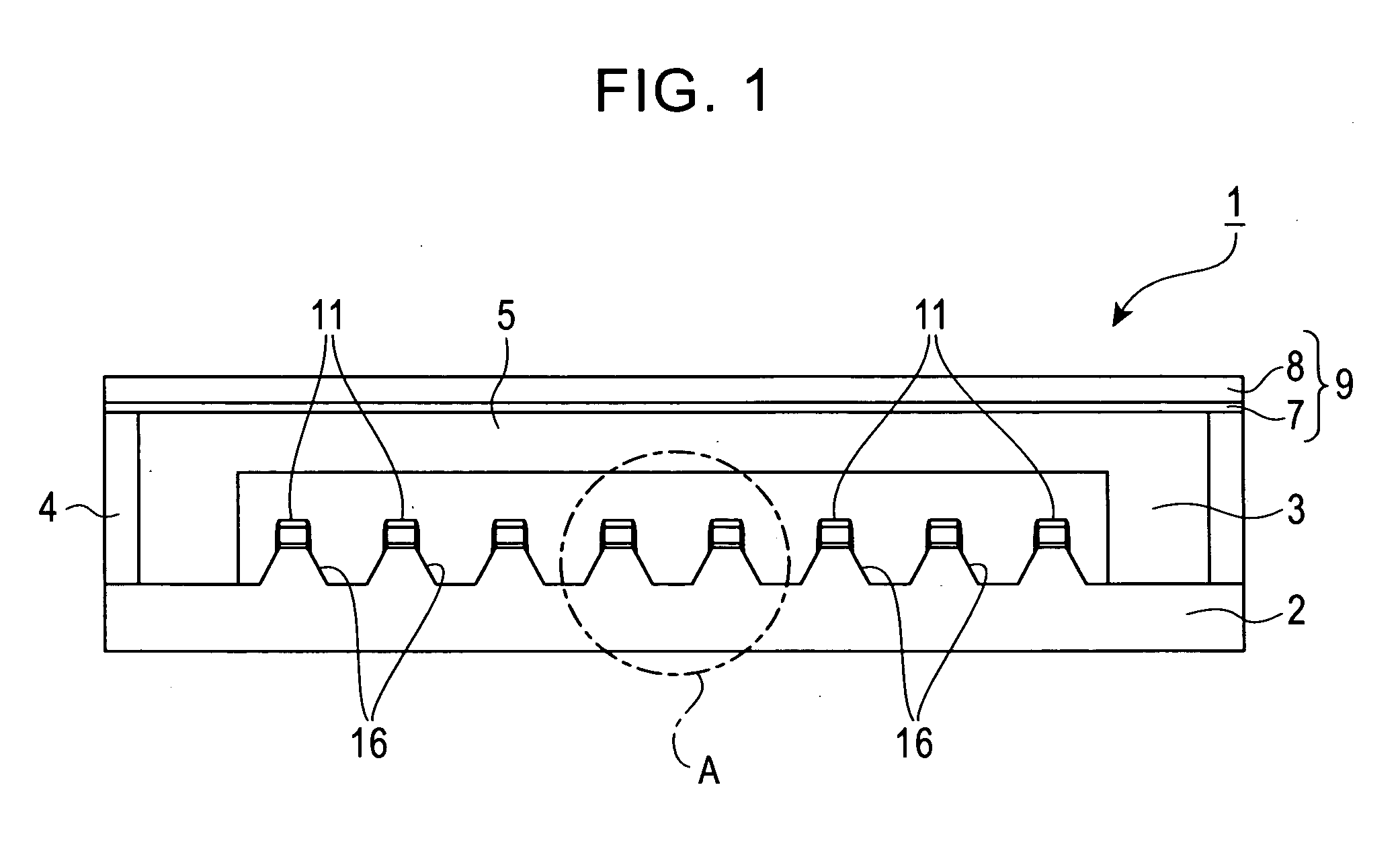
[0030]Referring to FIG. 1, an exemplary dye-sensitized solar cell 1 is described. The dye-sensitized solar cell 1 includes a glass substrate 2, and a porous layer (anode) 3 formed in a center part of an upper surface of the glass substrate 2. The solar cell 1 also includes a counter electrode (cathode) 9 made from an electroconductive metal plate 8. The counter electrode 9 is joined to the glass substrate 2 with a frame 4 held therebetween. The metal plate 8 is coated with a catalyst layer 7. The solar cell 1 also includes an electrolyte solution 5 between the porous layer 3 and the counter electrode 9. The glass substrate 2 is an insulating, translucent substrate. Translucency refers to the property of a material to allow light to pass therethough by virtue of being transparent, semi-transparent,...


PUM


Abstract

A method of readily forming a dye-sensitized solar cell having a porous layer of increased thickness. The dye-sensitized solar cell includes a translucent substrate, and a plurality of collecting electrode traces formed on the translucent substrate. The solar cell also includes a trench that is trapezoidal in cross-section and is formed on the translucent substrate between the collecting electrode traces. The solar cell also includes a porous layer upon which a sensitizing dye is adsorbed. The porous layer covers the translucent substrate within the trench and the collecting electrode traces.

Description

BACKGROUND OF THE INVENTION[0001]1. Field of the Invention[0002]The present invention relates to a dye-sensitized solar cell that converts solar energy to electrical energy using a dye, and also relates to a method of manufacturing the same.[0003]2. Description of the Related Art[0004]The amount of solar energy to which the earth is exposed is regarded to be 100,000 times the total amount of energy consumed by its inhabitants.[0005]Solar cells have a 50-year history as devices for converting this resource (sunlight) into electrical energy. The resulting electrical energy is readily used by man.[0006]Renewable energy obtained using solar cells or other means is recognized as an ideal resource because it places virtually no burden on the environment. However, it has not yet become widespread due to the high costs associated with generating electricity thereby.[0007]It is therefore necessary to lower the costs involved in generating electricity in order to invigorate the market, and cr...

Claims


Application Information

Patent Timeline
IPC IPC(8): H01L31/00H01L31/18
CPCH01G9/2031H01G9/2059Y02E10/542H01L51/445H01G9/2068Y02P70/50H10K30/83
Inventor MORI, HIROTAKA
Owner LAPIS SEMICON CO LTD
Learn More