Fuel injection control device and method of controlling fuel injection for an internal combustion engine

a technology of fuel injection control and internal combustion engine, which is applied in the direction of fuel injecting pump, liquid fuel feeder, machine/engine, etc., can solve the problems of large amount of smoke in exhaust gas, difficult to get on squish of fuel spray, and large diffusion of fuel spray, so as to achieve shortening of the total period of fuel injection and increasing the injection rate

Inactive Publication Date: 2010-01-21
TOYOTA JIDOSHA KK
View PDF12 Cites 12 Cited by
  • Summary
  • Abstract
  • Description
  • Claims
  • Application Information

AI Technical Summary

Benefits of technology

[0022]The invention provides a twin needle type fuel injection control device capable of ensuring a degree of freedom in the pattern of fuel injection corresponding to the range of operation with the aid of a single control valve, and a method of controlling fuel injection capable of achieving the same purpose.

Problems solved by technology

This is because, as shown in FIG. 30, the injection of fuel from the injection holes on the lower side (on the tip side) makes it difficult for fuel sprays to get on squish streams generated through the descent of a piston and the diffusion of fuel sprays is suppressed due to the influence of the squish streams.
On the other hand, at the time of intermediate / high load, the amount of smoke in exhaust gas is large as a result of a high combustion temperature.
However, as described above, in the case of the twin needle type fuel injection control device shown in FIG. 28 which is designed such that the outer needle valve and the inner needle valve are opened in this order without fail (i.e., the device designed such that the pressure in the single control chamber is controlled by the single open / close valve to adjust the lift amounts of the outer needle valve and the inner needle valve), there is a problem in that the degree of freedom in the pattern of fuel injection cannot be ensured.
In general, however, such open / close valves (control valves) are constructed using electromagnets, piezoelectric elements, or the like and hence are relatively large in size.
Accordingly, if the aforementioned construction requiring two control valves is adopted, there arises a new problem, namely, an increase in the size of the entire device.

Method used


Image

  • Fuel injection control device and method of controlling fuel injection for an internal combustion engine
  • Fuel injection control device and method of controlling fuel injection for an internal combustion engine
  • Fuel injection control device and method of controlling fuel injection for an internal combustion engine

Examples


first embodiment

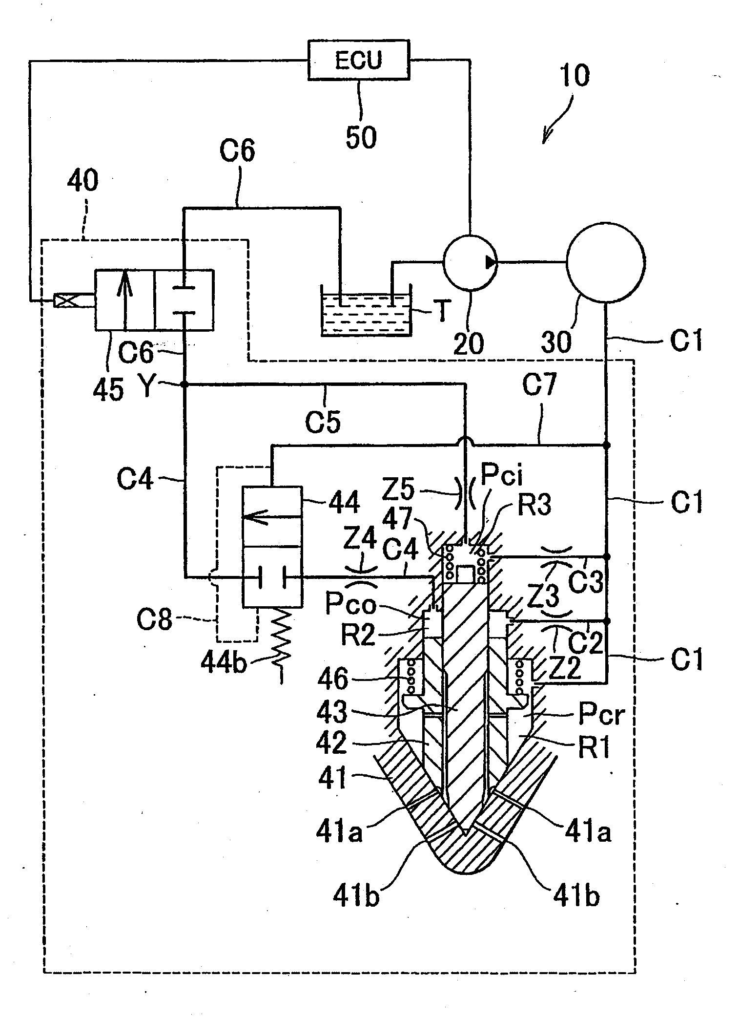
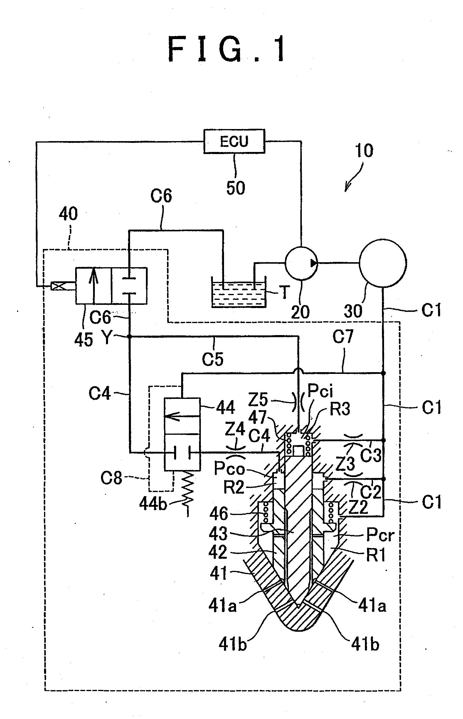
[0089]FIG. 1 shows a schematic construction of an entire fuel injection control device 10 for an internal combustion engine (diesel engine) according to the first embodiment of the invention. This fuel injection control device 10 is equipped with a fuel pump 20 for sucking / discharging fuel stored in a fuel tank T, a common rail 30 supplied with fuel discharged by the fuel pump 20 at a high pressure (hereinafter referred to as “a rail pressure Pcr”), an injector 40 supplied with fuel at the rail pressure Pcr from the common rail 30 through a fuel supply passage C1 to inject fuel into a combustion chamber (not shown) of the internal combustion engine, and an ECU 50 for controlling the fuel pump 20 and the injector 40. The fuel pump 20 and the common rail 30 correspond to the “high pressure generating portion”.

[0090]In FIG. 1, the single injector 40 supplied with fuel at the rail pressure Pcr from the common rail 30 through the single fuel supply passage C1 is shown. In fact, however, ...

second embodiment

[0136]Next, the fuel injection control device 10 for the internal combustion engine according to the second embodiment of the invention will be described. FIG. 5 shows a schematic construction of the entire device according to the second embodiment of the invention. In this second embodiment of the invention (as well as the other embodiments of the invention), constructional details / elements identical to those of the first embodiment of the invention are denoted respectively by the same reference symbols as in the first embodiment of the invention.

[0137]This second embodiment of the invention is different from the foregoing first embodiment of the invention in which the automatic valve 44 operates in accordance with the rail pressure Pcr itself, only in that the automatic valve 44 operates in accordance with a differential pressure ΔP (=Pcr−Pci) between the rail pressure Pcr and the inner control pressure Pci.

[0138]More specifically, as shown in FIG. 26, the automatic valve 44 of th...

modification example of second embodiment

[0148]Next, the fuel injection control device 10 for the internal combustion engine according to a modification example of the second embodiment of the invention will be described. FIG. 8 shows a schematic construction of the entire device according to this modification example of the second embodiment of the invention. This modification example of the second embodiment of the invention is different from the foregoing second embodiment of the invention in which the downstream end of the outer fuel outflow passage C4 meets with the downstream end of the inner fuel outflow passage C5 at the meeting portion Y, only in that the outer fuel outflow passage C4 is connected at the downstream end thereof to the fuel discharge passage C6 at a position downstream of the control valve 45.

[0149]FIGS. 9 and 10 each show an example of the operation of this modification example of the second embodiment of the invention. FIGS. 9 and 10 correspond to FIGS. 6 and 7 respectively. FIG. 9 shows an exampl...


PUM


Abstract

An outer needle valve (42) and an inner needle valve (43) face on back sides thereof an outer control chamber (R2) and an inner control chamber (R3), which are independent of each other, respectively. An outer fuel outflow passage (C4) and an inner fuel outflow passage (C5) for causing fuel to flow out from the outer control chamber (R2) and the inner control chamber (R3) respectively meet at a meeting portion (Y). A control valve (45) for rendering in communication / shutting off a fuel discharge passage (C6) for connecting the meeting portion (Y) to a fuel tank (T) is interposed in the fuel discharge passage (C6). An automatic valve (44) as an open / close valve for shutting off the outer fuel outflow passage (C4) when a rail pressure (Pcr) is equal to or lower than a predetermined value and rendering in communication the outer fuel outflow passage (C4) when the rail pressure (Pcr) is higher than the predetermined value is interposed in the outer fuel outflow passage (C4).

Description

BACKGROUND OF THE INVENTION[0001]1. Field of the Invention[0002]The invention relates to a fuel injection control device for an internal combustion engine and a method of controlling fuel injection for the internal combustion engine.[0003]2. Description of the Related Art[0004]Conventionally, as shown in FIG. 28, there has been known a so-called twin needle type fuel injection control device (e.g., see Japanese Patent Application Publication No. 2006-152893 (JP-A-2006-152893) and Japanese Patent Application Publication No. 2006-307832 (JP-A-2006-307832)) that is equipped with a body 110, an outer needle valve 120, an inner needle valve 130, a nozzle chamber 140, a control chamber 150, a fuel supply passage 160, a fuel inflow passage 170, a fuel discharge passage 180, and a control valve 190. The body 110 is equipped at a tip thereof, which faces a combustion chamber of an internal combustion engine (especially a diesel engine), with first injection holes (first injection hole group)...

Claims


Application Information

Patent Timeline
Patent Type & Authority Applications(United States)
IPC IPC(8): F02M69/54F02M47/00
CPCF02M45/086F02M47/027F02M2200/46F02M63/0225F02M61/182
Inventor FUTONAGANE, YOSHINORIOKUMURA, FUMIHIRONOMURA, SHIGEO
Owner TOYOTA JIDOSHA KK
Why Eureka
Try Eureka