
Driving apparatus for opening and closing body for vehicle

a technology for opening and closing the body and the driving apparatus, which is applied in the direction of gearing, magnetic circuit rotating parts, magnetic circuit shape/form/construction, etc., can solve the problems of limit in size and weight limit in cost reduction of the driving apparatus, etc., to achieve enhanced vehicle mountability, simplified wires and control logic to be connected to the electromagnetic clutch

Inactive Publication Date: 2013-06-27
MITSUBA CORP
View PDF10 Cites 13 Cited by
  • Summary
  • Abstract
  • Description
  • Claims
  • Application Information

AI Technical Summary

Benefits of technology

The present invention aims to provide a driving apparatus for opening and closing a slide door in a vehicle without using an electromagnetic clutch, which would limit the size and weight reduction of the apparatus. By eliminating the need for the electromagnetic clutch, the driving apparatus can be made smaller and lighter, and also more cost-efficient.

Problems solved by technology

Accordingly, there are limitations in size reduction and weight reduction of the driving apparatus.
Furthermore, since wires and control logic clutch are needed for driving the electromagnetic, there is also a limitation in cost reduction of the driving apparatus.

Method used


Image

  • Driving apparatus for opening and closing body for vehicle
  • Driving apparatus for opening and closing body for vehicle
  • Driving apparatus for opening and closing body for vehicle

Examples


first embodiment

[0033]Hereinafter, the present invention will be described in detail with reference to the drawings.

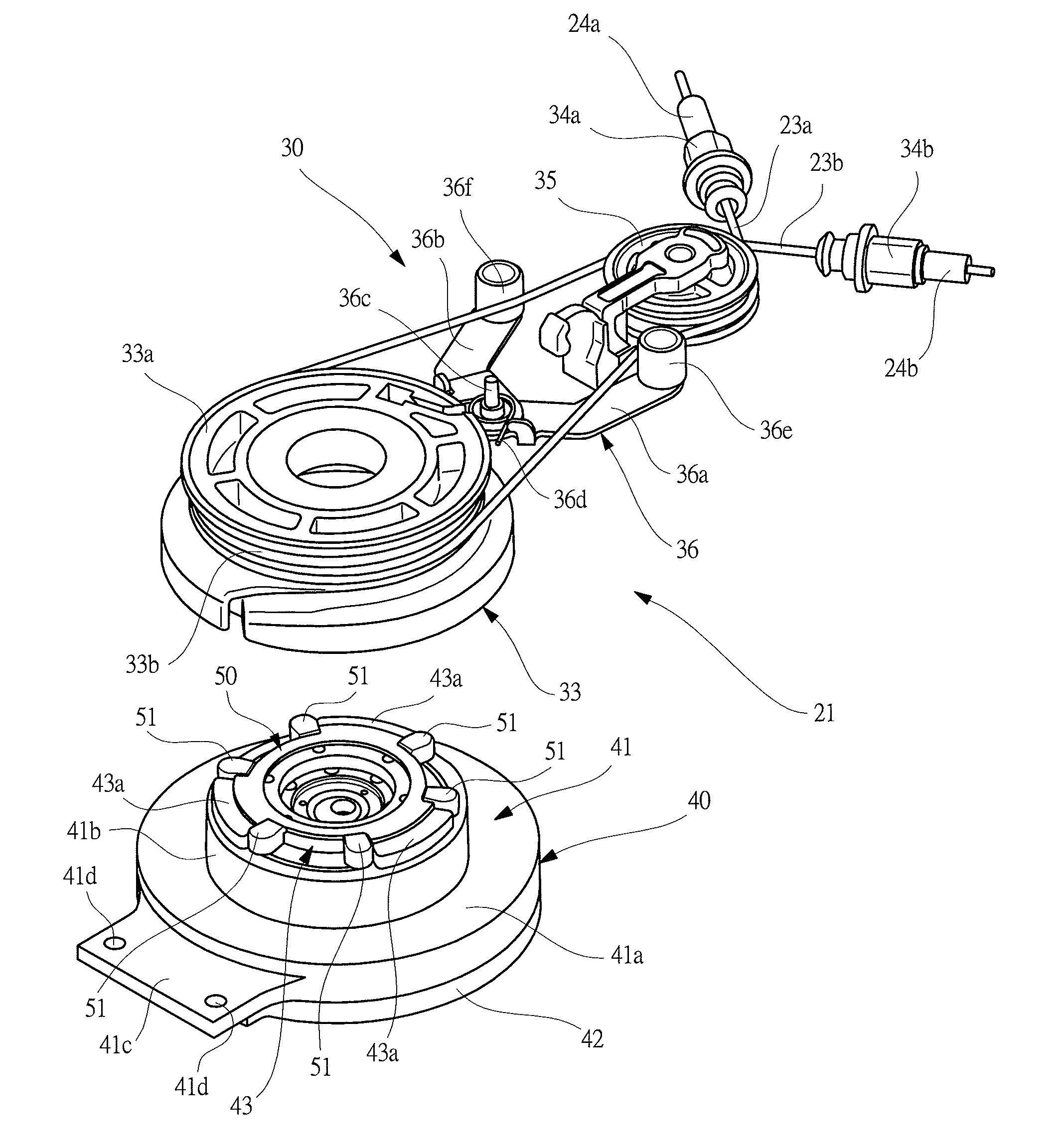
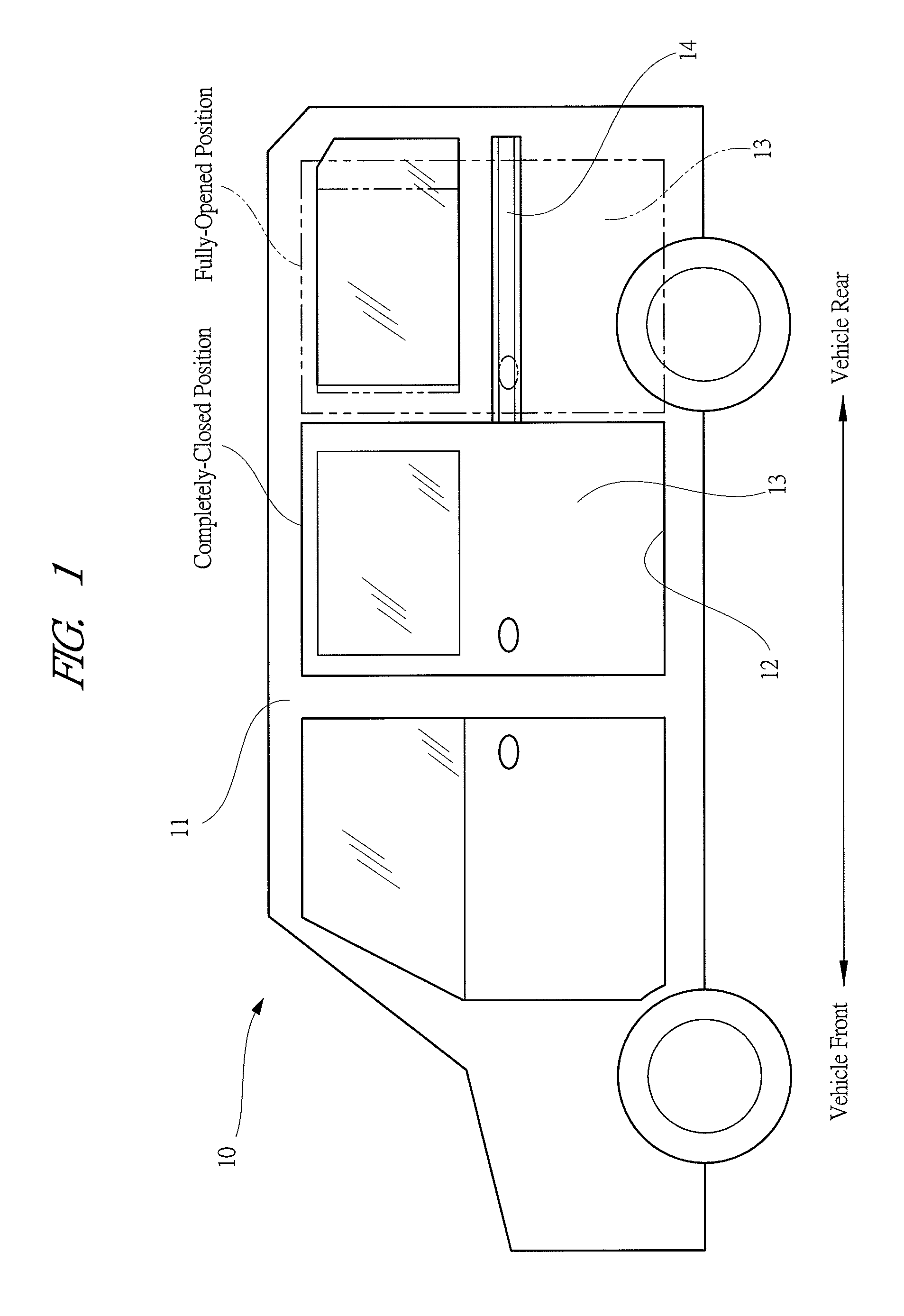
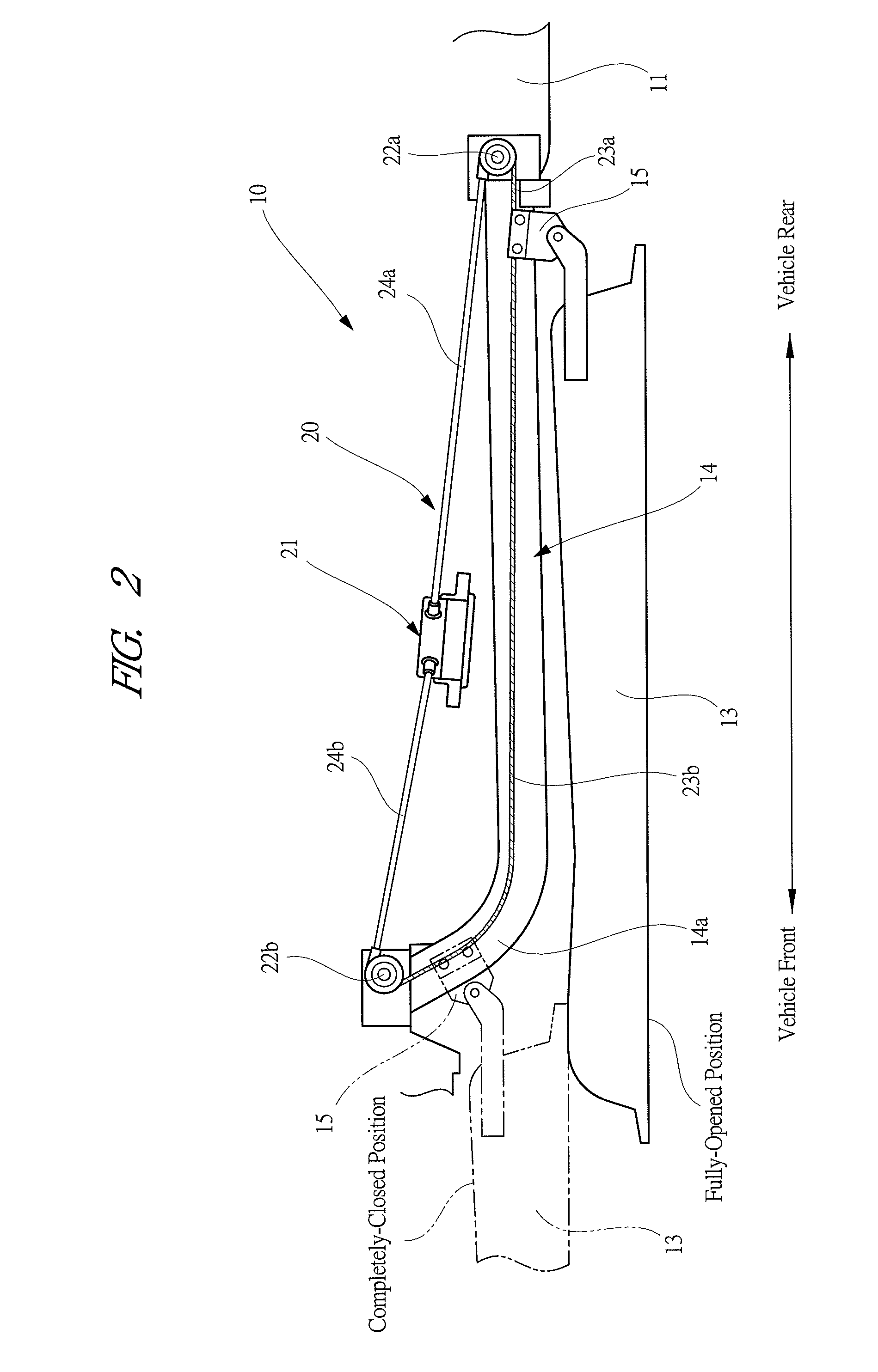
[0034]FIG. 1 is a side view showing a vehicle mounted with a driving apparatus according to the present invention, FIG. 2 is a plan view showing an attaching structure of a slide door, FIG. 3 is a perspective view showing an exterior appearance of the driving apparatus, FIG. 4 is a perspective view showing a drum unit and a motor unit, FIG. 5 is an exploded perspective view for explaining a detailed structure of a drum unit, FIG. 6 is an exploded perspective view for explaining a connecting structure of a drum, a damper member, and a torque transmitting member, FIG. 7 is a cross sectional view showing a detailed structure of a motor unit, FIG. 8A is an operation explaining view of an hypocycloid reducer of this embodiment, and FIG. 8B is an operation explaining view of another hypocycloid reducer (modification).

[0035]A vehicle 10 shown in FIG. 1 is, for example, an eight-seater statio...

second embodiment

[0083]FIG. 9 is a cross sectional view showing a detailed structure of a motor unit and FIG. 10 is an exploded perspective view for explaining a connecting structure of a rotor, a damper member, and an input member in the motor unit shown in FIG. 9.

[0084]As shown in FIG. 9, the second embodiment is different from the first embodiment in configurations of a motor unit 90 and a drum 120. Specifically, in the first embodiment, as shown in FIG. 6, the damper member 50 is provided between the torque transmitting plate (output member) 43 and the drum 33, while a damper member 104 is provided between a rotor 101 and a torque receiving member 107, and the drum 120 is directly fixed to the output rotation body 74 via a fastening screw S3 in the second embodiment.

[0085]A flat motor 100 serving as the electric motor rotationally driving the drum 120 is accommodated in the large diameter portion 41a of the motor case 41. The flat motor 100 is provided with a rotor 101 and the rotor 101 is prov...


PUM


Abstract

A hypocycloid reducer 70 for reducing rotation of a flat motor 60 to output the speed-reduced rotation to a drum is provided between the drum and the flat motor 60, a rotor shalt member 65 which is rotated with the same rotation number as the flat motor 60 is axially aligned with the drum is provided on the same side as the flat motor 60. An output rotation body 74 for outputting the speed-reduced rotation is axially aligned with the drum and provided on the same side as the drum. Since the rotor shaft member 65 and the output rotation body 74 are axially aligned with the drum, turning force can be transmitted bi-directionally between the rotor shaft member 65 and the output rotation body 74. Therefore, it is possible to eliminate an electromagnetic clutch to reduce the driving apparatus in size and weight, and since wires and control logic of the electromagnetic clutch are not needed for the driving apparatus, the driving apparatus can be reduced in production cost.

Description

CROSS REFERENCE TO RELATED APPLICATIONS[0001]This application is entitled to the benefit of and incorporates by reference essential subject matter disclosed in International Patent Application No. PCT / JP2011 / 0062793 filed on Jun. 3, 2011 and Japanese Patent Application No. 2010-129533 filed Jun. 7, 2010.TECHNICAL FIELD[0002]The present invention relates to a driving apparatus for driving an opening and closing body provided to a vehicle body to open and close the opening and closing body.BACKGROUND ART[0003]Conventionally, in a vehicle such as a station wagon and a minivan, a side portion of its body is provided with a sliding door (i.e., opening and closing body) which is opened and closed in vehicle-front and vehicle-back directions, thereby allowing passengers or baggage to be easily loaded or unloaded from the vehicle. This sliding door can normally be opened and closed by manual operation. However, in recent years, a driving apparatus is provided in the vicinity of a slide door...

Claims


Application Information

Patent Timeline
IPC IPC(8): B60J5/04E05F15/14
CPCE05F15/145H02K1/2733H02K5/24E05F15/146H02K7/1004E05Y2900/531Y10T74/18832H02K1/30H02K7/116B60J5/047E05F15/646E05F15/643
Inventor OKADA, MITSUHIRONAKAJIMA, RYUICHISAITO, TATSUYUKIYAMAGUCHI, ZENTARO
Owner MITSUBA CORP
Learn More