
Communication method and device

a communication method and signal technology, applied in the field of communication and transmission of signals, can solve the problems of increasing the reliability of signal transmission, increasing the difficulty of receiving and decoding, and increasing the difficulty of transmitting signals, so as to minimise the content of high frequency spectrum and wide separation

Active Publication Date: 2010-01-07
SATO HLDG CORP
View PDF6 Cites 10 Cited by
  • Summary
  • Abstract
  • Description
  • Claims
  • Application Information

AI Technical Summary

Benefits of technology

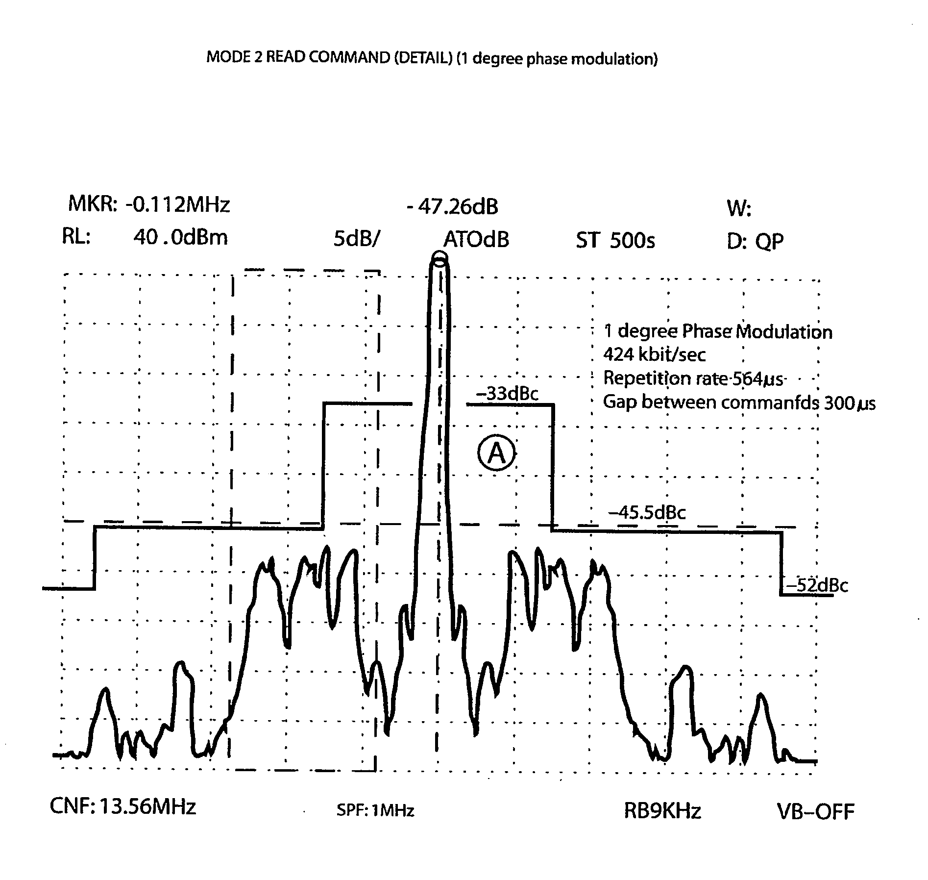
[0027]For PHPM the average spacing between phase transitions is at the baud rate unlike PPM where the spacing between amplitude transitions / changes is governed by the pulse width which is typically 10% of the baud rate. Accordingly compared to a PPM signal the spectrum of a PHPM signal is narrower and has lower high frequency content. PHPM has half the number of phase transitions compared to PPM amplitude transitions. Accordingly a PHPM signal will have half the spectral energy of an equivalent PPM signal. This allows the PHPM modulation level to be increased improving the detection reliability of a receiver.
[0029]Further improvements related to spectral occupancy and communication reliability are also provided in accordance with aspects of the present invention. Where PHPM encoding requires two transitions to be relatively close together the second transition may be suppressed and the correct data inferred from the absence of a transition. This ensures that there is always a relatively wide separation between transitions to minimise the high frequency spectrum content.
[0040]There is substantially no reduction in timing resolution required to detect PHPM / AMPM compared to the equivalent MFM encoding. This is a surprising result as fewer modulation changes are being used to transmit the same amount of data.

Problems solved by technology

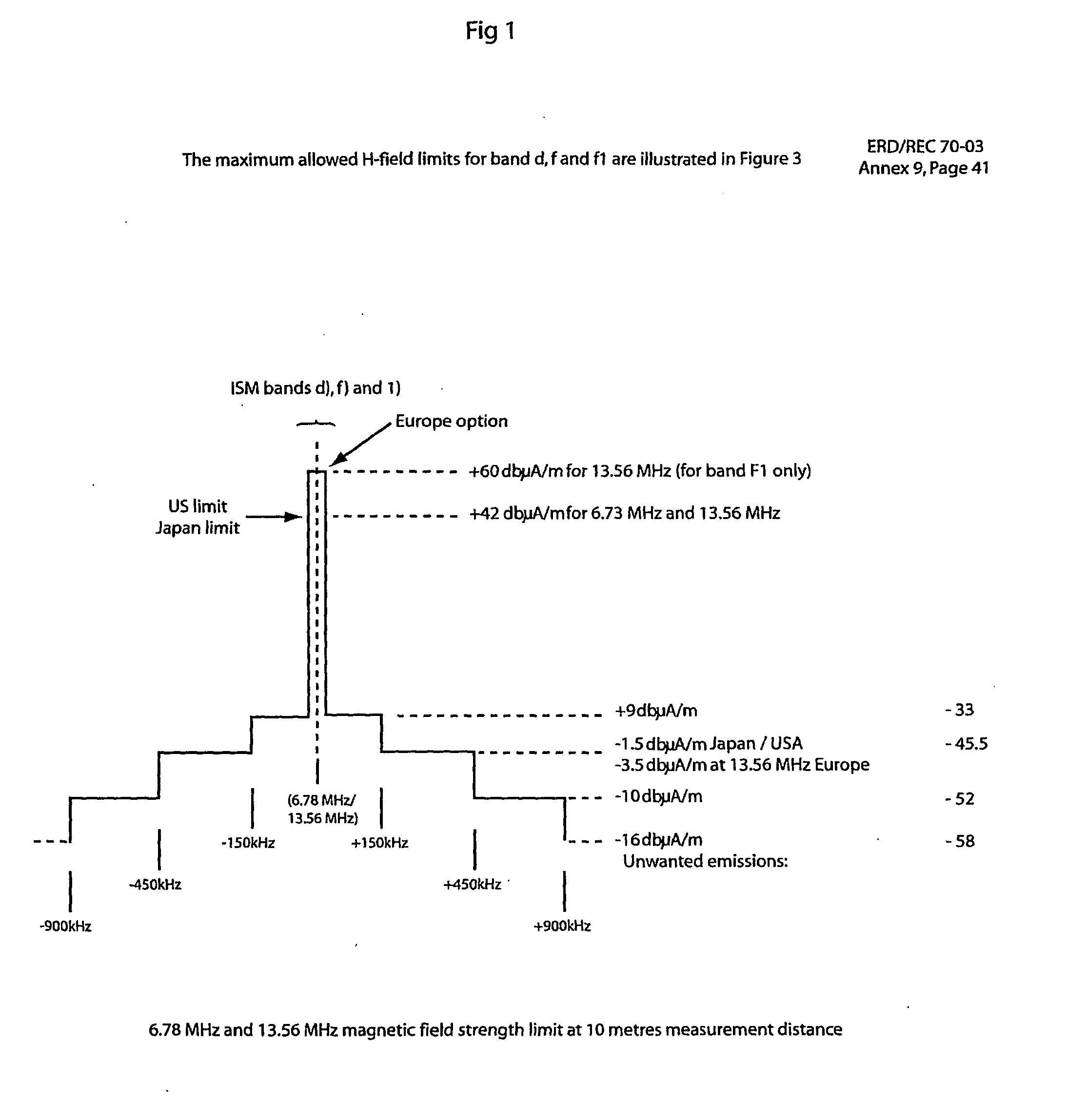
However, such a reduction in signal strength has also brought with it increased problems with the reliability of signal transmission.
Because the signal strength is reduced due to regulations imposed in various countries, the signals transmitted are increasingly susceptible to noise and other external factors and become increasing difficult to receive and decode, any one of which can interfere with reliable signal transmission.
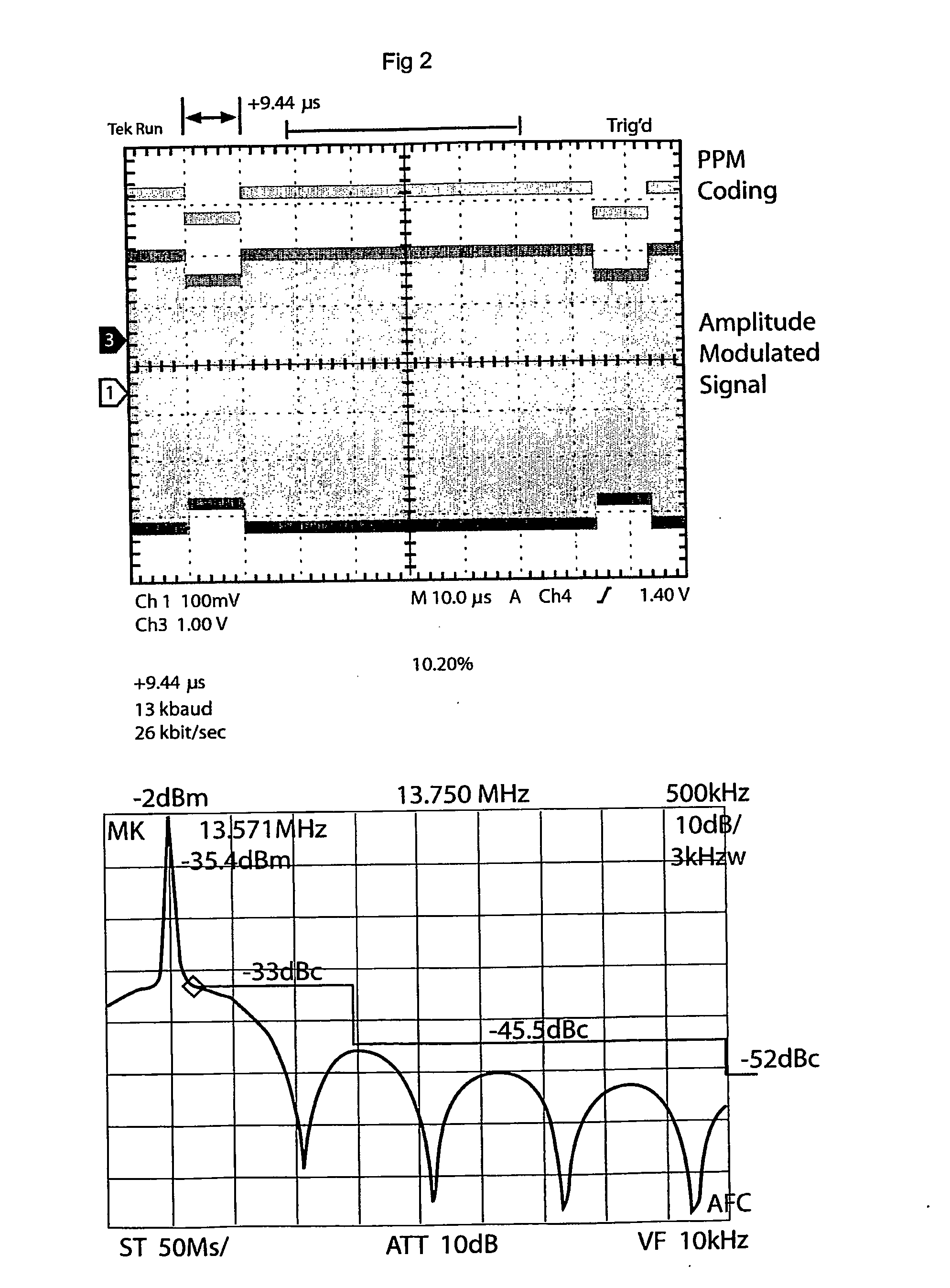
However, this transmission is at 26 Kbit / s, 13K Baud and is thus considered to have a relatively slow bit rate and relatively slow baud rate.
Accordingly, this transmission standard is not considered suitable for a number of applications, such as RFID application in which high speed RF signal transmissions are required.
However, the transmission of MFM is considered susceptible to noise and other external factors and impact on the reliability of the signal transmission.

Method used


Image

  • Communication method and device
  • Communication method and device
  • Communication method and device

Examples


Embodiment Construction

[0060]FIG. 7 illustrates 1 out of 4 pulse position modulation (PPM). The coding effected by pulse position modulation for 1 out of 4 mode is shown according to the standard ISO / IEC 18000-3:2004(E). It can be seen that the position of the transmitted pulse (relative to time) indicates whether the received signal will be interpreted as a ‘00’, ‘01’, ‘10’, or ‘11’. FIG. 8 illustrates an example of 1 out of 4 PPM as applied to the binary 01001011.

[0061]It is well understood that when the bit pairs ‘00’, ‘01’, ‘10’ and ‘11’ are represented by modulation symbols these modulation symbols are called bauds. A baud is a modulation symbol that can represent one bit or multiple bits depending upon the method of encoding used. For example in 1 out of 4 PPM each baud (pulse) represents 2 bits.

[0062]FIG. 9 illustrates an example of 1 out of 4 Phase Position Modulation (PHPM). Advantageously, the present invention ultilises a change of phase (relative to a time / position) to indicate a particular co...


PUM


Abstract

The present invention relates to the field of communication and transmission of signals. In particular, the present invention relates to a new communication and / or modulation method. The present invention also relates to improving channel occupancy. The present specification discloses the adoption of phase transitions / changes in a manner that indicates a code by virtue of their position (timing) in the communication. This is referred to as Phase Position Modulation.

Description

FIELD OF INVENTION[0001]The present invention relates to the field of communication and transmission of signals. In particular, the present invention relates to a new communication and / or modulation method. The present invention also relates to improving channel occupancy.[0002]In one form, the invention relates to RF signal transmission, for example, a RF signal transmission adapted for use in an RFID (Radio Frequency Identification) system.[0003]In another form, the present invention has particular application to Phase Jitter Modulation signal communication, such as that disclosed in PCT / AU98 / 01077 (WO 99 / 34526) entitled ‘A transmitter and a method for transmitting data’. The present invention also has application to other types of signal transmissions.[0004]It will be convenient to hereinafter describe the invention in relation to RF signal transmission, however it should be appreciated that the present invention is not limited to that use only.BACKGROUND ART[0005]The discussion ...

Claims


Application Information

Patent Timeline
Patent Type & Authority Applications(United States)
IPC IPC(8): H04L27/04
CPCH04L25/4902
Inventor MURDOCH, GRAHAM ALEXANDER MUNROLITTLECHILD, STUART COLIN
Owner SATO HLDG CORP
Learn More