Method and apparatus for the reliquefaction of a vapour

Inactive Publication Date: 2010-01-07
CRYOSTAR
View PDF10 Cites 22 Cited by
  • Summary
  • Abstract
  • Description
  • Claims
  • Application Information

AI Technical Summary

Benefits of technology

[0004]Nowadays, it is preferred to employ a non-combustible gas as the working fluid. Further, in order to reduce the work of compression that needs to be supplied externally, it is preferred to employ an expansion turbine rather than a valve in order to expand the working fluid.
[0009]EP-A-1 132 698 discloses a method that mitigates the problems that are caused when vapour is returned with condensed natural gas to a liquefied natural gas (LNG) storage tank.
[0011]Since the nitrogen mole fraction in the liquefied natural gas is less than the nitrogen mole fraction in the boiled-off vapour and even less than that in flash gas formed by the expansion through the valve of the condensed boil-off vapour, dilution of the boiled-off vapour with the liquefied natural gas either upstream or downstream of the condenser, or both, tends to dampen swings in the composition of the vapour phase in the storage tank that would otherwise occur without the mixing of the boiled off vapour or natural gas condensate with the liquefied natural gas from storage.
[0015]The method and apparatus according to the invention are able to achieve improved thermodynamic efficiency of operation in comparison with the corresponding methods and apparatuses disclosed in the prior documents mentioned above. We attribute the improved thermodynamic efficiency to the integration of the working fluid cycle and the natural gas condensation not only in the condenser but also in the second and third heat exchangers. The improvement in thermodynamic efficiency can be exploited by means of a reduced power consumption.

Problems solved by technology

Since methane is recognised as a greenhouse gas such a practice would be environmentally unacceptable.
Another problem associated with the operation of the apparatus according to WO-A-98 / 43029, is that there are considerable thermodynamic inefficiencies caused by a mismatch between, on the one hand, the temperature and enthalpy of the compressed natural gas and, on the other hand, the temperature and enthalpy of the working fluid.
Since the nitrogen mole fraction in the liquefied natural gas is less than the nitrogen mole fraction in the boiled-off vapour and even less than that in flash gas formed by the expansion through the valve of the condensed boil-off vapour, dilution of the boiled-off vapour with the liquefied natural gas either upstream or downstream of the condenser, or both, tends to dampen swings in the composition of the vapour phase in the storage tank that would otherwise occur without the mixing of the boiled off vapour or natural gas condensate with the liquefied natural gas from storage.
The method according to EP-A-1 132 698 does not however greatly enhance the overall thermodynamic efficiency.

Method used


Image

  • Method and apparatus for the reliquefaction of a vapour
  • Method and apparatus for the reliquefaction of a vapour

Examples


Embodiment Construction

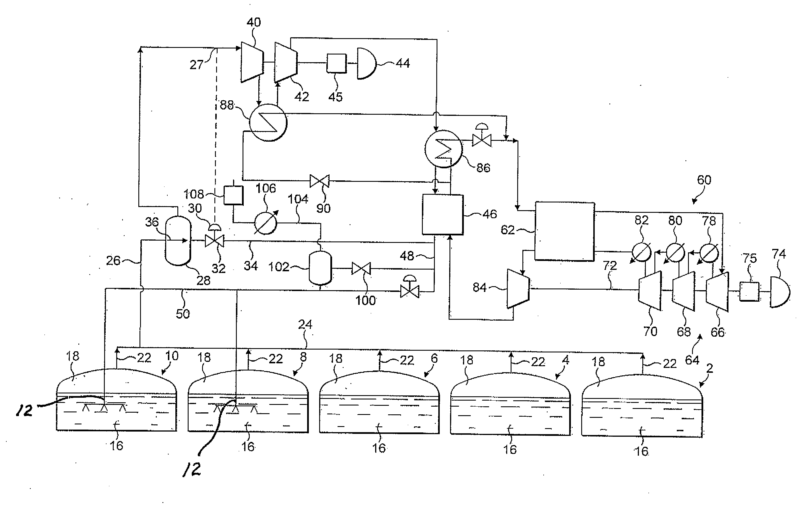
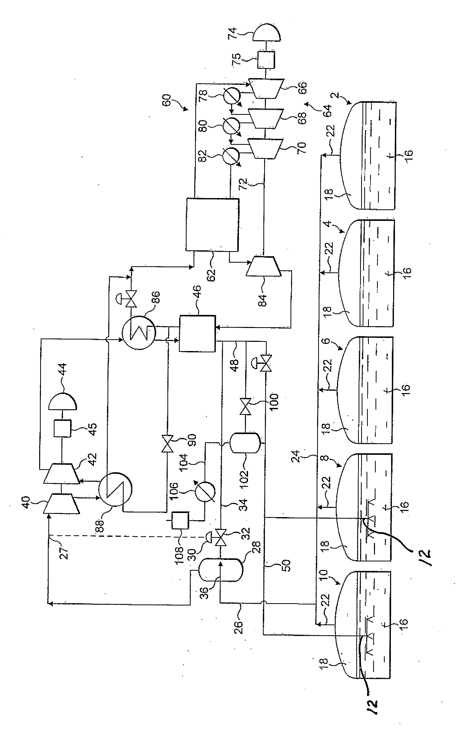
[0023]Referring to the drawing, the five thermally-insulated storage tanks 2, 4, 6, 8 and 10 are provided in the hull of a ship or other sea-going vessel (not shown). Two or more of the storage tanks 2, 4, 6, 8 and 10 are provided with a submerged orifice pipe 12 located in its bottom region through which LNG is introduced. For reasons of ease of illustration, the orifice pipes in the tanks 2, 4 and 6 are not shown in the drawing. If only some of the storage tanks are provided with submerged orifice pipes, redistribution of returning LNG to tanks not so provided is by operation of liquid pumps (not shown). The orifice pipe 12 is in normal operation submerged in a volume 16 of LNG. In each of the tanks 2, 4, 6, 8 and 10 there is a vapour space 18 above the volume 16 of LNG therein.

[0024]Although the storage tanks 2, 4, 6, 8 and 10 are thermally insulated, because LNG has a boiling point at normal pressures substantially below ambient temperature there is a continuous evaporation of t...


PUM


Abstract

Boiled off liquefied natural gas flows from a storage tank and is compressed in vapour compression stages. The resulting compressed vapour is condensed in a condenser and the condensate returned to the tank. The condenser is cooled by a working fluid, for example nitrogen, flowing in a Brayton cycle. The Brayton cycle includes a heat exchanger which removes heat of compression from the compressed natural gas vapour upstream of its passage through the condenser. In addition a part of the working fluid is withdrawn from a region of the Brayton cycle intermediate the working fluid outlet from the condenser and the working fluid inlet to the heat exchanger and the withdrawn working fluid flows through another heat exchanger in which it removes heat of compression from the natural gas vapour intermediate the compression stages. The withdrawn working fluid is returned to the Brayton cycle.

Description

[0001]This invention relates to a method and apparatus for the reliquefication of a vapour, particularly a method and apparatus which are operable on board ship to reliquefy natural gas vapour.[0002]Natural gas is conventionally transported over large distances in liquefied state. For example, ocean going tankers are used to convey liquefied natural gas from a first location in which the natural gas is liquefied to a second location in which it is vaporised and sent to a gas distribution system. Since natural gas liquefies at cryogenic temperatures, i.e.. temperatures below −100° C., there will be continuous boil-off of the liquefied natural gas in any practical storage system. Accordingly, apparatus needs to be provided in order to reliquefy the boiled-off vapour. In such an apparatus a refrigeration cycle is performed comprising compressing a working fluid in a plurality of compressors, cooling the compressed working fluid by indirect heat exchange, expanding the working fluid, an...

Claims


Application Information

Patent Timeline
IPC IPC(8): F25J1/00
CPCF17C2221/033F25J2245/02F17C2223/033F17C2250/0439F17C2265/03F17C2265/034F17C2265/037F17C2270/0105F25J1/0025F25J1/0045F25J1/005F25J1/0072F25J1/0204F25J1/0208F25J1/0277F25J1/0288F25J2205/30F25J2220/62F25J2230/04F25J2230/08F25J2230/60F17C2223/0161F25J2210/04F25J1/0265F25J1/0292F17C9/00F25J1/02
Inventor FUCHS, VINCENT
Owner CRYOSTAR
Why Eureka
Try Eureka