
MgO Tunnel Barriers and Method of Formation

a tunnel barrier and tunnel magnetoresistance technology, applied in the field of magnetoresistance devices at the magnetic tunnel junction (mtj) and the like, can solve the problems of reducing tmr, reducing tmr, and mgo was a poor choice for tunneling barriers, so as to improve tunnel magnetoresistance and improve performance. , the effect of increasing the spin polarization valu

Inactive Publication Date: 2009-12-31
INT BUSINESS MASCH CORP
View PDF13 Cites 28 Cited by
  • Summary
  • Abstract
  • Description
  • Claims
  • Application Information

AI Technical Summary

Benefits of technology

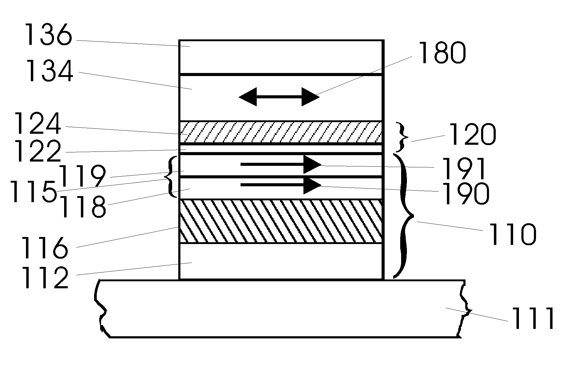
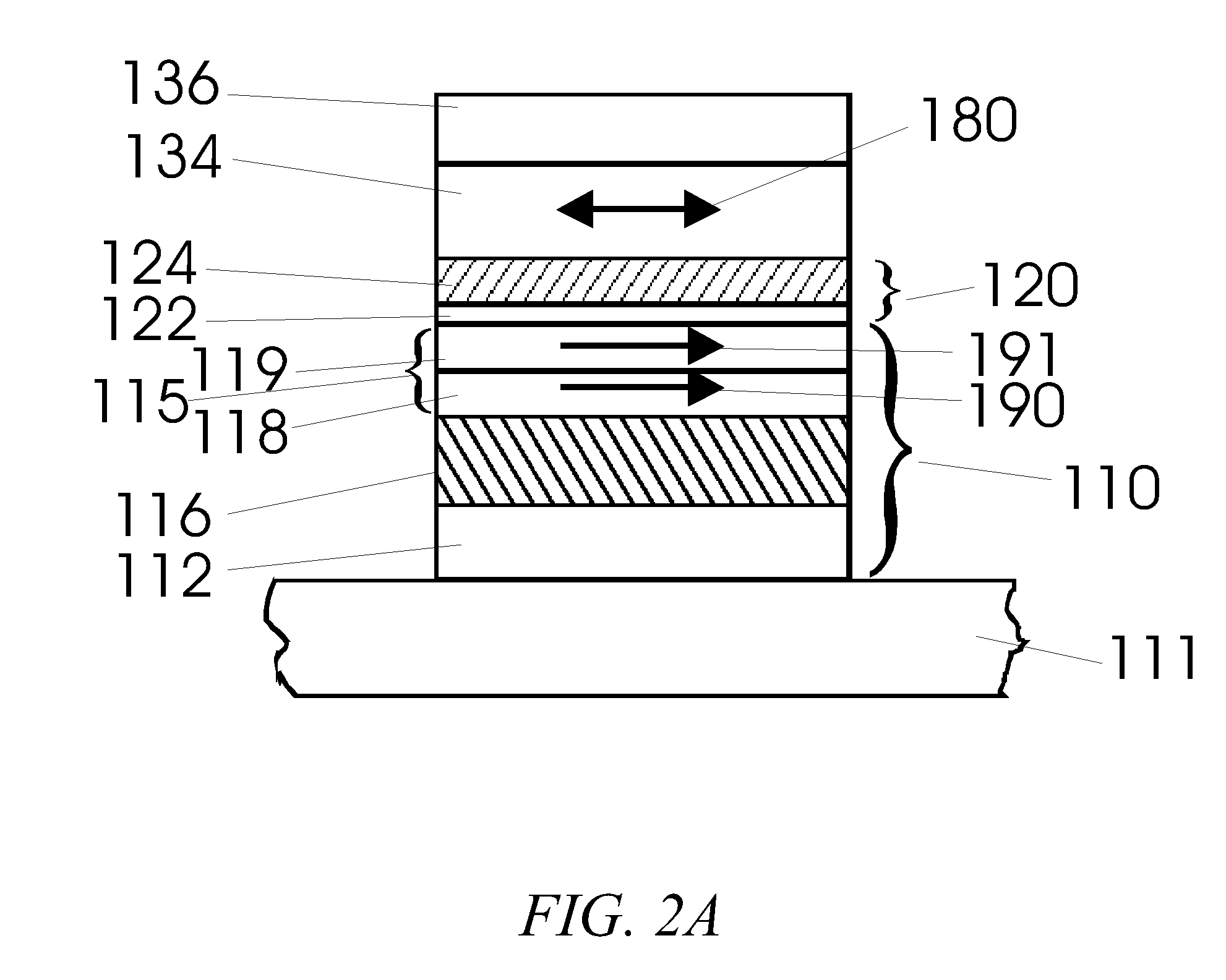
[0020]Methods are disclosed in which a MgO tunnel barrier is prepared with improved performance. In particular, the MgO barrier can be formed without oxidizing the lower ferromagnetic (or ferrimagnetic) electrode in magnetic tunnel junction devices, so as to give much higher tunnel magnetoresistance values than in the prior art. Similarly, much higher spin polarization values of tunneling current are obtained in tunnel junction devices with one or more ferromagnetic (or ferrimagnetic) electrodes. The MgO tunnel barrier so formed does not have a significant number of defects that would otherwise lead to hopping conductivity through the tunnel barrier. In preferred methods, highly oriented (100) MgO barriers are formed without using single crystalline substrates or high deposition temperatures, thereby facilitating the manufacture of devices using standard deposition techniques on polycrystalline or amorphous films. Post anneal treatments are preferred to improve the tunneling magnetoresistance, which can exceed 160% at room temperature.
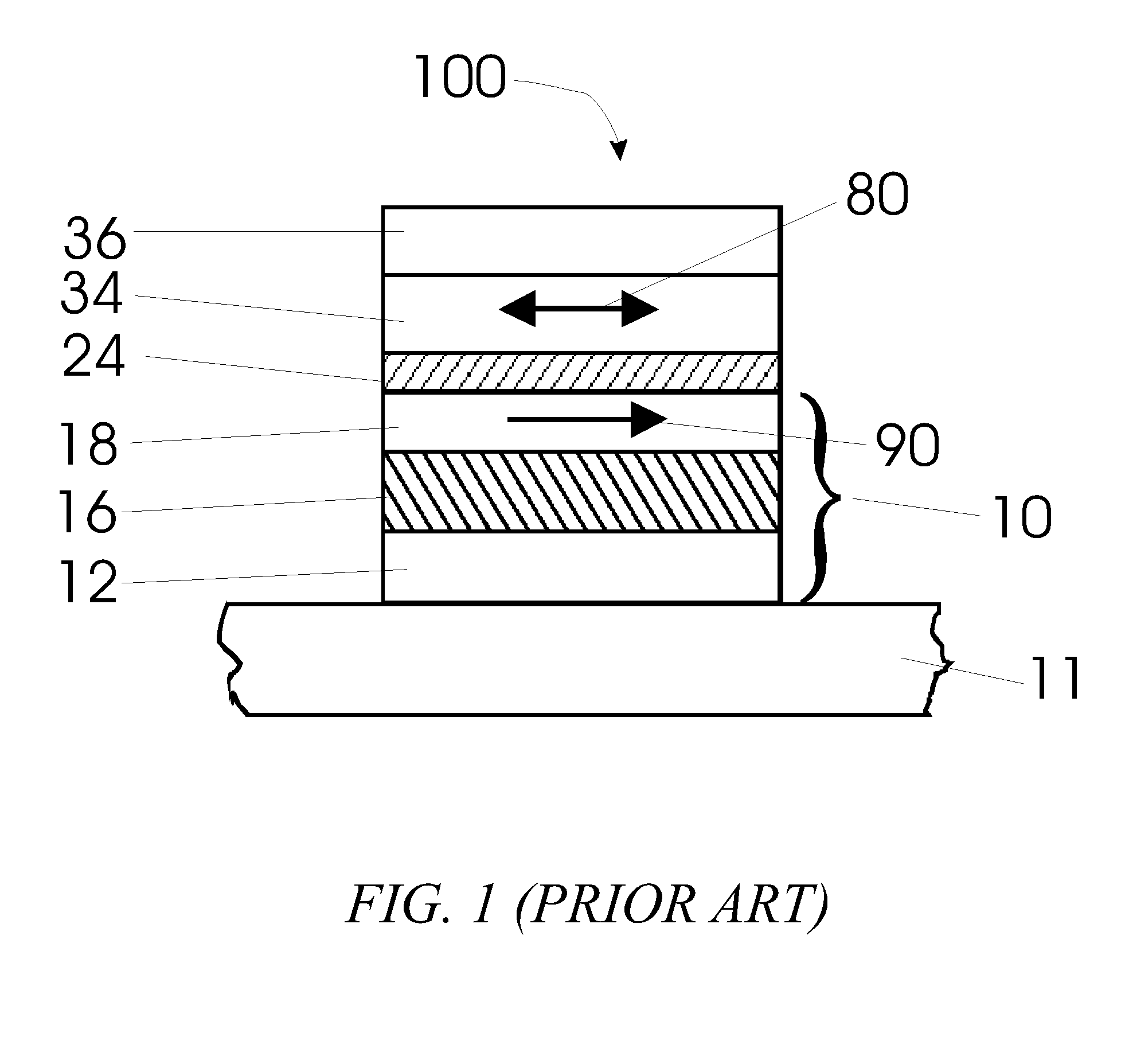
[0023]Another aspect of the invention is a method that includes providing a ferromagnetic underlayer having a surface that is substantially free of oxide and forming a Mg layer on the surface to both protect the underlayer from oxidation and to wet the underlayer. Oxygen and additional Mg are then directed onto the metal layer to form a MgO tunnel barrier that is in contact with the underlayer, in which the ferromagnetic underlayer is selected to be bcc and at least partially (100) oriented to improve the performance of the tunnel barrier. In a preferred implementation, a ferromagnetic overlayer is formed over the MgO tunnel barrier (e.g., directly on the MgO tunnel barrier, if no spacer layer is used) to form a magnetic tunnel junction, and the MgO tunnel junction is annealed to improve its performance. The tunnel junction is preferably annealed at a temperature selected to yield a tunnel magnetoresistance that is greater than 100% at room temperature, more preferably greater than 140% at room temperature, and still more preferably greater than 160% at room temperature. The tunnel junction is preferably annealed at a temperature greater than 200° C. (e.g., in the range of 200° C. to 400° C.), and more preferably at a temperature greater than 350° C. (e.g., the range of 350° C. to 400° C.). Preferably, the ferromagnetic material of the overlayer and the ferromagnetic material of the underlayer, as well as the MgO tunnel barrier, are substantially (100) oriented. The Mg layer deposited onto the surface of the underlayer preferably has a thickness of between 3 and 20 angstroms.
[0024]In a further aspect of the invention, there is provided a method that includes depositing Mg onto a surface of an underlayer to form a Mg layer thereon, in which the surface is selected to be substantially free of oxide. The method further includes directing additional Mg, in the presence of oxygen, towards the Mg layer to form a MgO tunnel barrier that is in contact with the underlayer, in which the oxygen reacts with the additional Mg and the Mg layer to form the MgO tunnel barrier, and annealing the MgO tunnel barrier to improve its performance. The thickness of the Mg layer is preferably selected to be large enough to prevent oxidation of the underlayer but small enough that, upon reaction of the oxygen with the Mg layer, substantially all the Mg in the Mg layer is converted into MgO. The Mg layer preferably has a thickness of between 3 and 20 angstroms, more preferably between 4 and 8 angstroms, and still more preferably between 3 and 8 angstroms. In one preferred method, the underlayer includes a semiconductor, such as GaAs. In another preferred method, an overlayer is formed on the MgO tunnel barrier, in which one of the overlayer and the underlayer includes a non-ferromagnetic, non-ferrimagnetic metal layer, and the other of the overlayer and the underlayer includes a ferrimagnetic layer.
[0032]Performance of the MgO tunnel barriers disclosed herein may be improved through annealing, wherein performance refers to various attributes of the MgO tunnel barrier or associated device. For example, annealing a magnetic tunnel junction improves, in particular, its magneto-tunneling resistance; annealing a tunnel barrier improves, in particular, its spin polarization; annealing a MIM or a capacitor improves, in particular, its leakage current or barrier height.

Problems solved by technology

Incomplete or under-oxidation of the barrier may lead to “pin-holes” in the barrier which will usually result in a diminishment of the TMR.
On the other hand, over-oxidation of the barrier or excess oxygen within the barrier or at the barrier surface will result in oxidation of the ferromagnetic electrodes which also usually results in decreased TMR.
These authors concluded that MgO was a very poor choice for a tunneling barrier in MTJs.
However, although the crystalline quality of these films was very good, this group found no evidence for significant tunneling magnetoresistance in their samples.
Although this group was able to prepare high quality epitaxial tunnel junctions, these junctions showed poor TMR, with TMR values at low temperatures (4.2 K) of only 22.9%.
The resistance of the tunnel junctions was found to decrease substantially with temperature, which Mitani et al. argued was due to poor quality MgO tunnel barriers with defects in the barrier, which resulted in hopping conductivity of the tunneling electrons through these defects.
However, the devices of Tsuge have considerably lower tunnel magnetoresistance values than those fabricated using other prior art methods of forming the tunnel barrier and magnetic tunnel junction.
Evidently, Tsuge does not demonstrate any improvement over the prior art because the heat of formation of the metal oxide versus the formation of the ferromagnetic oxide is not the critical parameter in determining whether oxygen from the ferromagnetic oxide will diffuse away from this layer into the metal oxide layer.
Thus, all the oxygen sites in the metal oxide layer will be occupied, which does not allow for the diffusion of oxygen from the ferromagnetic oxide layer.
Moreover, the diffusion of oxygen through a ferromagnetic oxide layer is likely to be small, so that the diffusion of oxygen from the ferromagnetic oxide into the metal oxide layer will require extreme conditions of high temperature.
Also, Hibino does not discuss or teach the use of preferred crystallographic orientations of his tunnel barriers.

Method used


Image

  • MgO Tunnel Barriers and Method of Formation
  • MgO Tunnel Barriers and Method of Formation
  • MgO Tunnel Barriers and Method of Formation

Examples


Embodiment Construction

[0050]To date the tunneling barrier that has been most extensively studied for MTJs is alumina (Al2O3), where the ferromagnetic electrodes are typically formed from various Ni—Fe or Co—Fe or Ni—Co—Fe alloys. While a wide variety of methods have been used to deposit the alumina tunneling barrier, perhaps the most widely used method is one in which a thin layer of metallic Al is first deposited. Subsequently this layer is oxidized, either by “natural oxidation”, in which the Al layer is exposed to oxygen or air, or by plasma oxidation, in which the Al layer is placed in an oxygen plasma and the Al layer is often electrically biased by a few volts to enhance the plasma oxidation. The Al layer can also be oxidized by a beam of energetic oxygen ions. For thinner Al layers, it is usually preferred to oxidize the Al layer by natural oxidation. In view of this prior art method of forming Al2O3, the formation of MgO tunneling barriers was extensively studied by first depositing thin Mg layer...


PUM

PropertyMeasurementUnit
thicknessaaaaaaaaaa
thicknessaaaaaaaaaa
temperatureaaaaaaaaaa

Abstract

MgO tunnel barriers are formed by depositing a thin layer of Mg on a suitable underlayer, and then directing oxygen and additional Mg towards the Mg layer. The oxygen reacts with the additional Mg and the Mg in the Mg layer to form a MgO tunnel barrier that enjoys excellent tunneling characteristics. The MgO tunnel barriers so formed may be used in magnetic tunnel junctions having tunneling magnetoresistance (TMR) values of greater than 100%. The highest TMR values are observed for junctions that have been annealed and that have a (100) crystallographic orientation.

Description

[0001]This application is a divisional of Applicant's copending U.S. application Ser. No. 10 / 973,954 filed Oct. 25, 2004, which in turn is a continuation of U.S. application Ser. No. 10 / 824,835 filed Apr. 14, 2004 and entitled “MgO Tunnel Barriers and Method of Formation” (now abandoned), which in turn is a continuation-in-part of U.S. application Ser. No. 10 / 646,246 filed Aug. 22, 2003 and entitled “MgO Tunnel Barriers and Method of Formation” (now abandoned), all of which are hereby incorporated by reference.[0002]The U.S. Government has a paid-up license in this invention and the right in limited circumstances to require the patent owner to license others on reasonable terms as provided for by the terms of contract MDA972-99-C-0009 awarded by DARPA.TECHNICAL FIELD[0003]The invention relates to magnetic tunnel junction (MTJ) magnetoresistive (MR) devices for use as magnetic field sensors such as read heads for reading magnetically recorded data, as memory cells in nonvolatile magn...

Claims


Application Information

Patent Timeline
Patent Type & Authority Applications(United States)
IPC IPC(8): B05D5/12
CPCH01L43/08H01L43/12H01L43/10H10N50/01H10N50/85H10N50/10
Inventor PARKIN, STUART STEPHEN PAPWORTH
Owner INT BUSINESS MASCH CORP
Learn More