System and Method For Test Tube and Cap Identification

a technology of test tube and cap, applied in the field of machine vision systems, can solve the problems of limiting the processing techniques that may be employed, adversely affecting the accuracy of the results obtained from the processing of image contents, etc., and achieve the effect of accurate and efficient identification of natur

Active Publication Date: 2009-12-31
NOVANTA CORP
View PDF13 Cites 84 Cited by
  • Summary
  • Abstract
  • Description
  • Claims
  • Application Information

AI Technical Summary

Benefits of technology

The present invention provides a system and method for identifying the contents of images captured by a machine vision system. It can identify the type of test tube in a rack handling system and determine if it is associated with a cap. This information can be provided to the main line processing of the sample handling machine to assist with identification and processing of samples. The invention uses an optical imager and a microcontroller to extract barcode information, interpret visual information, and make accurate and efficient identifications.

Problems solved by technology

However, the characteristics of digital images taken by machine vision systems, such as the contrast of the image, often limit the processing techniques that may be employed and adversely affects the accuracy of the results obtained from the processing of the image contents.

Method used


Image

  • System and Method For Test Tube and Cap Identification
  • System and Method For Test Tube and Cap Identification
  • System and Method For Test Tube and Cap Identification

Examples


Embodiment Construction

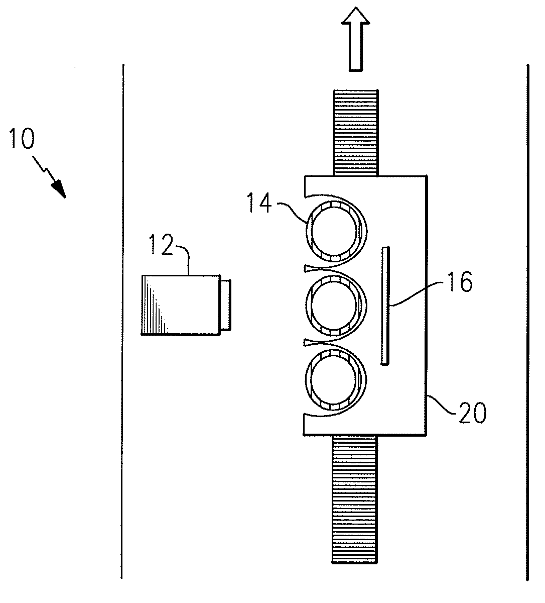
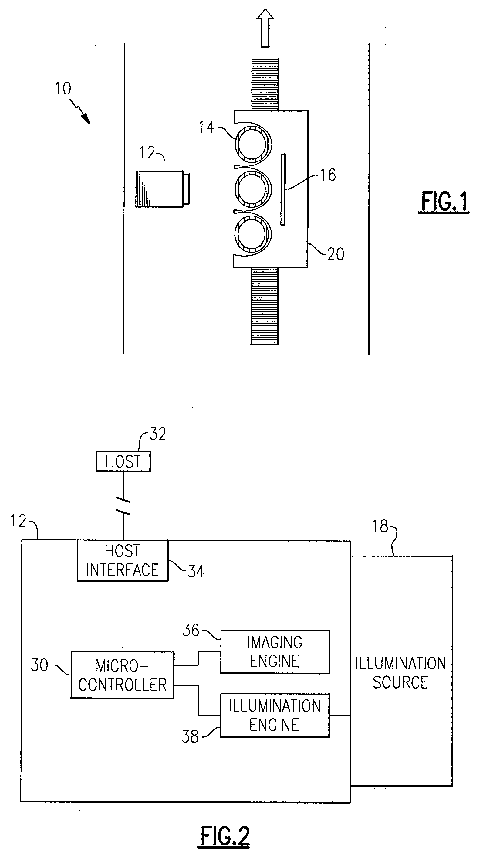
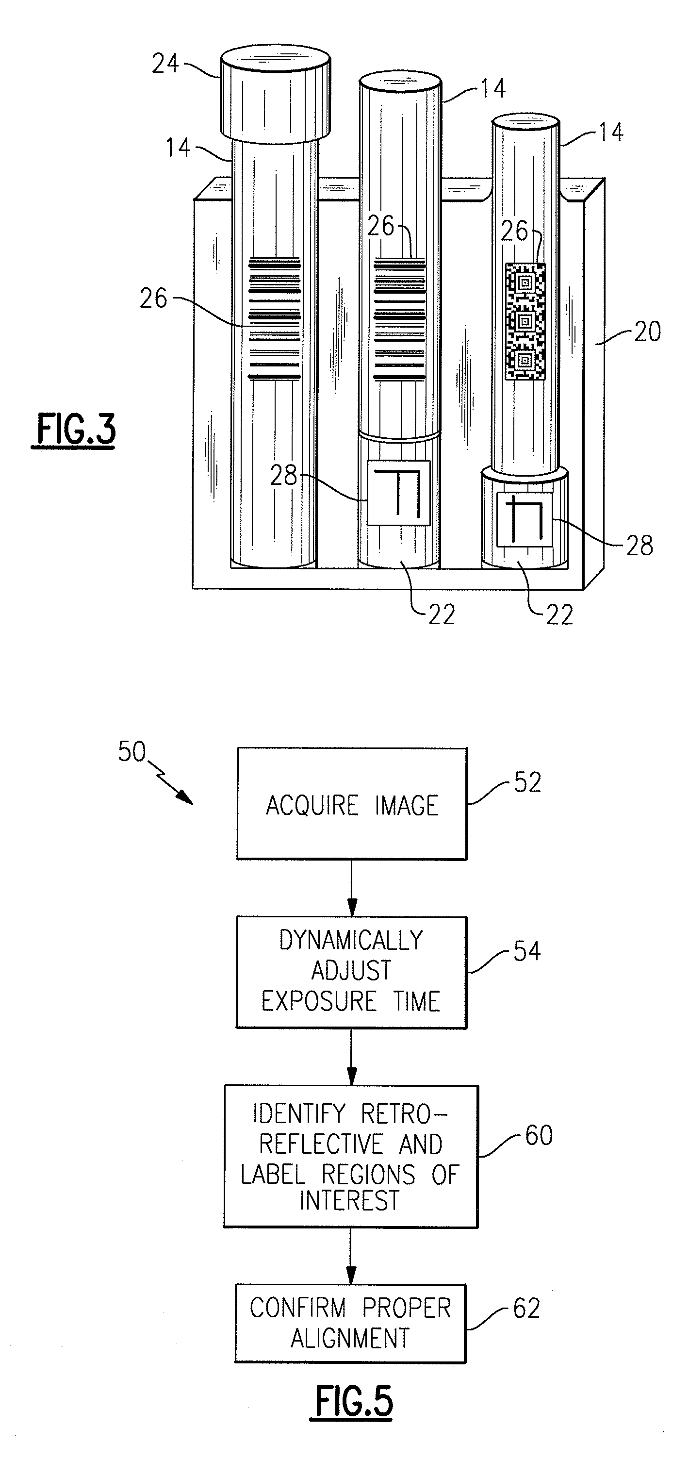
[0035]Referring now to the drawings, wherein like numerals refer to like parts throughout, there is seen in FIG. 1, a machine vision system 10 according to the present invention. System 10 comprises an optical imager 12 positioned on one side of a target, such as such as one or more test tubes 14. Preferably, a retro-reflective background 16 is positioned behind test tube 14 in alignment with imager 12 to reflect light onto the rear of tube 14.

[0036]Imager 12 preferably comprises a complementary metal oxide semiconductor (CMOS) image sensor and is capable of reading and interpreting two-dimensional images, such as 1D linear codes, 2D stacked / matrix codes, OCR fonts, RSS (Reduced Space Symbology) codes, and postal codes, as well as provides image capturing for use in a wide range of applications, such as image and shape recognition, signature capture, image capture, and optical character recognition (OCR). As seen in FIG. 2, imager 12 may include an on-board illumination source 18 co...


PUM


Abstract

A system for identifying test tube types and properties in a sample handling machine using visual information automatically obtained by an optical imager and then processed using vision processing methods. The system includes an optical imager positioned to capture images containing one or more test tubes in a rack and a microcontroller programmed to extract predetermined regions of interest and interpret the optical information in the image to decipher the dimension of the test tubes, determine the presence or absence of caps on the test tubes, decode any encoded data, and interpret custom symbologies. The system may then determine the nature of the test tubes or other containers presented before the image and provide that information to the sample handling machine to assist with processing of samples.

Description

BACKGROUND[0001]1. Field of Invention[0002]The present invention relates to machine vision systems and, more specifically, to a system and method for determining the nature of a test tube and associated cap using optical imaging techniques.[0003]2. Background of the Art[0004]Machine vision plays an important role in automated and robotic systems, such as assembly line manufacturing, quality control inspection, and sample processing. Conventional systems are generally comprised of an optical imager, such as a charged coupled device (CCD) or similar device using digital imaging technology, that is positioned to capture images of objects that pass in front of it. In low-light or enclosed applications, machine vision systems may include an illumination source, such as a bank of light emitting diodes (LEDs), positioned proximately to the imager. The images are subsequently processed to decode information contained in the resulting two-dimensional image, such as 1D linear codes, 2D stacke...

Claims


Application Information

Patent Timeline
Patent Type & Authority Applications(United States)
IPC IPC(8): G06K9/00G06K9/46G06V10/25
CPCB01L3/5453G01N35/00732G06T2207/30108G06K9/3233G06T7/0008G01N2035/00752G06V10/25
Inventor CHEN, MO
Owner NOVANTA CORP
Why Eureka
Try Eureka